


Create successful ePaper yourself
Turn your PDF publications into a flip-book with our unique Google optimized e-Paper software.
Philips Semiconductors Preliminary <strong>User</strong> <strong>Manual</strong><br />
ARM-based Microcontroller<br />
PWM Latch Enable Register (PWMLER - 0xE0014050)<br />
<strong>LPC2131</strong>/<strong>2132</strong>/<strong>2138</strong><br />
The PWM Latch Enable Register is used to control the update of the PWM Match registers when they are used for PWM<br />
generation. When software writes to the location of a PWM Match register while the Timer is in PWM mode, the value is held in<br />
a shadow register. When a PWM Match 0 event occurs (normally also resetting the timer in PWM mode), the contents of shadow<br />
registers will be transferred to the actual Match registers if the corresponding bit in the Latch Enable Register has been set. At<br />
that point, the new values will take effect and determine the course of the next PWM cycle. Once the transfer of new values has<br />
taken place, all bits of the LER are automatically cleared. Until the corresponding bit in the PWMLER is set and a PWM Match 0<br />
event occurs, any value written to the PWM Match registers has no effect on PWM operation.<br />
For example, if PWM2 is configured for double edge operation and is currently running, a typical sequence of events for changing<br />
the timing would be:<br />
Write a new value to the PWM Match1 register.<br />
Write a new value to the PWM Match2 register.<br />
Write to the PWMLER, setting bits 1 and 2 at the same time.<br />
The altered values will become effective at the next reset of the timer (when a PWM Match 0 event occurs).<br />
The order of writing the two PWM Match registers is not important, since neither value will be used until after the write to<br />
PWMLER. This insures that both values go into effect at the same time, if that is required. A single value may be altered in the<br />
same way if needed.<br />
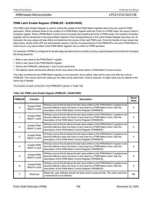
The function of each of the bits in the PWMLER is shown in Table 140.<br />
Table 142: PWM Latch Enable Register (PWMLER - 0xE0014050)<br />
PWMLER Function Description<br />
0<br />
1<br />
2<br />
3<br />
4<br />
5<br />
6<br />
Enable PWM<br />
Match 0 Latch<br />
Enable PWM<br />
Match 1 Latch<br />
Enable PWM<br />
Match 2 Latch<br />
Enable PWM<br />
Match 3 Latch<br />
Enable PWM<br />
Match 4 Latch<br />
Enable PWM<br />
Match 5 Latch<br />
Enable PWM<br />
Match 6 Latch<br />
7 Reserved<br />
Writing a one to this bit allows the last value written to the PWM Match 0 register to be<br />
become effective when the timer is next reset by a PWM Match event. See the<br />
description of the PWM Match Control Register (PWMMCR).<br />
Writing a one to this bit allows the last value written to the PWM Match 1 register to be<br />
become effective when the timer is next reset by a PWM Match event. See the<br />
description of the PWM Match Control Register (PWMMCR).<br />
Writing a one to this bit allows the last value written to the PWM Match 2 register to be<br />
become effective when the timer is next reset by a PWM Match event. See the<br />
description of the PWM Match Control Register (PWMMCR).<br />
Writing a one to this bit allows the last value written to the PWM Match 3 register to be<br />
become effective when the timer is next reset by a PWM Match event. See the<br />
description of the PWM Match Control Register (PWMMCR).<br />
Writing a one to this bit allows the last value written to the PWM Match 4 register to be<br />
become effective when the timer is next reset by a PWM Match event. See the<br />
description of the PWM Match Control Register (PWMMCR).<br />
Writing a one to this bit allows the last value written to the PWM Match 5 register to be<br />
become effective when the timer is next reset by a PWM Match event. See the<br />
description of the PWM Match Control Register (PWMMCR).<br />
Writing a one to this bit allows the last value written to the PWM Match 6 register to be<br />
become effective when the timer is next reset by a PWM Match event. See the<br />
description of the PWM Match Control Register (PWMMCR).<br />
Reserved, user software should not write ones to reserved bits. The value read from<br />
a reserved bit is not defined.<br />
Reset<br />
Value<br />
Pulse Width Modulator (PWM) 196 November 22, 2004<br />
0<br />
0<br />
0<br />
0<br />
0<br />
0<br />
0<br />
NA


