


Create successful ePaper yourself
Turn your PDF publications into a flip-book with our unique Google optimized e-Paper software.
Philips Semiconductors Preliminary <strong>User</strong> <strong>Manual</strong><br />
ARM-based Microcontroller<br />
Slave Transmitter Mode:<br />
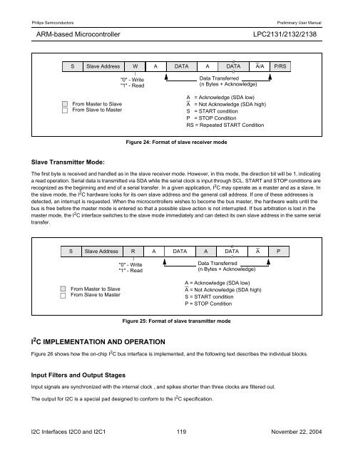
Figure 24: Format of slave receiver mode<br />
<strong>LPC2131</strong>/<strong>2132</strong>/<strong>2138</strong><br />
S Slave Address W A DATA A DATA A/A P/RS<br />
From Master to Slave<br />
From Slave to Master<br />
The first byte is received and handled as in the slave receiver mode. However, in this mode, the direction bit will be 1, indicating<br />
a read operation. Serial data is transmitted via SDA while the serial clock is input through SCL. START and STOP conditions are<br />
recognized as the beginning and end of a serial transfer. In a given application, I 2 C may operate as a master and as a slave. In<br />
the slave mode, the I 2 C hardware looks for its own slave address and the general call address. If one of these addresses is<br />
detected, an interrupt is requested. When the microcontrollers wishes to become the bus master, the hardware waits until the<br />
bus is free before the master mode is entered so that a possible slave action is not interrupted. If bus arbitration is lost in the<br />
master mode, the I 2 C interface switches to the slave mode immediately and can detect its own slave address in the same serial<br />
transfer.<br />
I 2 C IMPLEMENTATION AND OPERATION<br />
Figure 25: Format of slave transmitter mode<br />
Figure 26 shows how the on-chip I 2 C bus interface is implemented, and the following text describes the individual blocks.<br />
Input Filters and Output Stages<br />
"0" - Write<br />
"1" - Read<br />
Input signals are synchronized with the internal clock , and spikes shorter than three clocks are filtered out.<br />
The output for I2C is a special pad designed to conform to the I 2 C specification.<br />
Data Transferred<br />
(n Bytes + Acknowledge)<br />
A = Acknowledge (SDA low)<br />
A = Not Acknowledge (SDA high)<br />
S = START condition<br />
P = STOP Condition<br />
RS = Repeated START Condition<br />
S Slave Address R A<br />
DATA A DATA A P<br />
From Master to Slave<br />
From Slave to Master<br />
"0" - Write<br />
"1" - Read<br />
Data Transferred<br />
(n Bytes + Acknowledge)<br />
A = Acknowledge (SDA low)<br />
A = Not Acknowledge (SDA high)<br />
S = START condition<br />
P = STOP Condition<br />
I2C Interfaces I2C0 and I2C1 119 November 22, 2004


