


You also want an ePaper? Increase the reach of your titles
YUMPU automatically turns print PDFs into web optimized ePapers that Google loves.
Philips Semiconductors Preliminary <strong>User</strong> <strong>Manual</strong><br />
ARM-based Microcontroller<br />
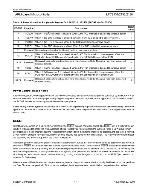
Table 24: Power Control for Peripherals Register for <strong>LPC2131</strong>/<strong>2132</strong>/<strong>2138</strong> (PCONP - 0xE01FC0C4)<br />
PCONP Function Description<br />
Power Control Usage Notes<br />
<strong>LPC2131</strong>/<strong>2132</strong>/<strong>2138</strong><br />
7 PCI2C0 When 1, the I 2 C0 interface is enabled. When 0, the I 2 C0 interface is disabled to conserve power. 1<br />
8 PCSPI0 When 1, the SPI0 interface is enabled. When 0, the SPI0 is disabled to conserve power. 1<br />
9 PCRTC When 1, the RTC is enabled. When 0, the RTC is disabled to conserve power. 1<br />
10 PCSPI1 When 1, the SSP interface is enabled. When 0, the SSP is disabled to conserve power. 1<br />
11 Reserved <strong>User</strong> software should write 0 here to reduce power consumption. 1<br />
12 PCAD0<br />
After every reset, PCONP register contains the value that enables all interfaces and peripherals controlled by the PCONP to be<br />
enabled. Therefore, apart from proper configuring via peripheral dedicated registers, user’s application has no need to access<br />
the PCONP in order to start using any of the on-board peripherals.<br />
Power saving oriented systems should have 1s in the PCONP register only in positions that match peripherals really used in the<br />
application. All other bits, declared to be "Reserved" or dedicated to the peripherals not used in the current application, must be<br />
cleared to 0.<br />
RESET<br />
When 1, A/D converter 0 is enabled. When 0, A/D 0 is disabled to conserve power. Clear the<br />
PDN bit in the AD0CR before clearing this bit, and set this bit before setting PDN.<br />
18:13 Reserved<br />
Reserved, user software should not write ones to reserved bits. The value read from a reserved<br />
bit is not defined.<br />
0<br />
19 PCI2C1 When 1, the I 2 C1 interface is enabled. When 0, the I 2 C1 interface is disabled to conserve power. 1<br />
20 PCAD1<br />
31:21 Reserved<br />
When 1, A/D converter 1 is enabled. When 0, A/D 1 is disabled to conserve power. Clear the<br />
PDN bit in the AD0CR before clearing this bit, and set this bit before setting PDN.<br />
Reserved, user software should not write ones to reserved bits. The value read from a reserved<br />
bit is not defined.<br />
Reset<br />
Value<br />
Reset has two sources on the <strong>LPC2131</strong>/<strong>2132</strong>/<strong>2138</strong>: the RESET pin and Watchdog Reset. The RESET pin is a Schmitt trigger<br />
input pin with an additional glitch filter. Assertion of chip Reset by any source starts the Wakeup Timer (see Wakeup Timer<br />
description later in this chapter), causing reset to remain asserted until the external Reset is de-asserted, the oscillator is running,<br />
a fixed number of clocks have passed, and the on-chip circuitry has completed its initialization. The relationship between Reset,<br />
the oscillator, and the Wakeup Timer are shown in Figure 11.<br />
The Reset glitch filter allows the processor to ignore external reset pulses that are very short, and also determines the minimum<br />
duration of RESET that must be asserted in order to guarantee a chip reset. Once asserted, RESET pin can be deasserted only<br />
when crystal oscillator is fully running and an adequate signal is present on the X1 pin of the <strong>LPC2131</strong>/<strong>2132</strong>/<strong>2138</strong>. Assuming that<br />
an external crystal is used in the crystal oscillator subsystem, after power on, the RESET pin should be asserted for 10 ms. For<br />
all subsequent resets when crystal oscillator is already running and stable signal is on the X1 pin, the RESET pin needs to be<br />
asserted for 300 ns only.<br />
When the internal Reset is removed, the processor begins executing at address 0, which is initially the Reset vector mapped from<br />
the Boot Block. At that point, all of the processor and peripheral registers have been initialized to predetermined values.<br />
System Control Block 47 November 22, 2004<br />
1<br />
1<br />
0


