


You also want an ePaper? Increase the reach of your titles
YUMPU automatically turns print PDFs into web optimized ePapers that Google loves.
Philips Semiconductors Preliminary <strong>User</strong> <strong>Manual</strong><br />
ARM-based Microcontroller<br />
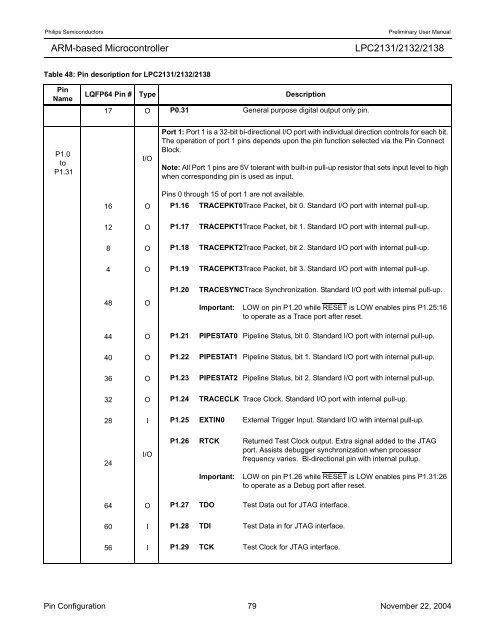
Table 48: Pin description for <strong>LPC2131</strong>/<strong>2132</strong>/<strong>2138</strong><br />
Pin<br />
Name<br />
P1.0<br />
to<br />
P1.31<br />
LQFP64 Pin # Type Description<br />
17 O P0.31 General purpose digital output only pin.<br />
I/O<br />
<strong>LPC2131</strong>/<strong>2132</strong>/<strong>2138</strong><br />
Port 1: Port 1 is a 32-bit bi-directional I/O port with individual direction controls for each bit.<br />
The operation of port 1 pins depends upon the pin function selected via the Pin Connect<br />
Block.<br />
Note: All Port 1 pins are 5V tolerant with built-in pull-up resistor that sets input level to high<br />
when corresponding pin is used as input.<br />
Pins 0 through 15 of port 1 are not available.<br />
16 O P1.16 TRACEPKT0Trace Packet, bit 0. Standard I/O port with internal pull-up.<br />
12 O P1.17 TRACEPKT1Trace Packet, bit 1. Standard I/O port with internal pull-up.<br />
8 O P1.18 TRACEPKT2Trace Packet, bit 2. Standard I/O port with internal pull-up.<br />
4 O P1.19 TRACEPKT3Trace Packet, bit 3. Standard I/O port with internal pull-up.<br />
48 O<br />
P1.20 TRACESYNCTrace Synchronization. Standard I/O port with internal pull-up.<br />
Important: LOW on pin P1.20 while RESET is LOW enables pins P1.25:16<br />
to operate as a Trace port after reset.<br />
44 O P1.21 PIPESTAT0 Pipeline Status, bit 0. Standard I/O port with internal pull-up.<br />
40 O P1.22 PIPESTAT1 Pipeline Status, bit 1. Standard I/O port with internal pull-up.<br />
36 O P1.23 PIPESTAT2 Pipeline Status, bit 2. Standard I/O port with internal pull-up.<br />
32 O P1.24 TRACECLK Trace Clock. Standard I/O port with internal pull-up.<br />
28 I P1.25 EXTIN0 External Trigger Input. Standard I/O with internal pull-up.<br />
24<br />
I/O<br />
P1.26 RTCK Returned Test Clock output. Extra signal added to the JTAG<br />
port. Assists debugger synchronization when processor<br />
frequency varies. Bi-directional pin with internal pullup.<br />
Important: LOW on pin P1.26 while RESET is LOW enables pins P1.31:26<br />
to operate as a Debug port after reset.<br />
64 O P1.27 TDO Test Data out for JTAG interface.<br />
60 I P1.28 TDI Test Data in for JTAG interface.<br />
56 I P1.29 TCK Test Clock for JTAG interface.<br />
Pin Configuration 79 November 22, 2004


