


You also want an ePaper? Increase the reach of your titles
YUMPU automatically turns print PDFs into web optimized ePapers that Google loves.
Philips Semiconductors Preliminary <strong>User</strong> <strong>Manual</strong><br />
ARM-based Microcontroller<br />
<strong>LPC2131</strong>/<strong>2132</strong>/<strong>2138</strong><br />
SIC is the I 2 C Interrupt Clear bit. Writing a 1 to this bit clears the SI bit in the I2CONSET register. Writing 0 has no effect.<br />
STAC is the Start flag Clear bit. Writing a 1 to this bit clears the STA bit in the I2CONSET register. Writing 0 has no effect.<br />
I2ENC is the I 2 C Interface Disable bit. Writing a 1 to this bit clears the I2EN bit in the I2CONSET register.Writing 0 has no effect.<br />
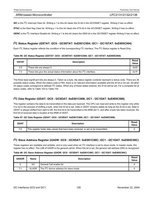
I 2 C Status Register (I2STAT: I2C0 - I2C0STAT: 0xE001C004; I2C1 - I2C1STAT: 0xE005C004)<br />
Each I 2 C Status register reflects the condition of the corresponding I 2 C interface. The I 2 C Status register is Read-Only.<br />
Table 96: I2C Status Register (I2STAT: I2C0 - I2C0STAT: 0xE001C004; I2C1 - I2C1STAT: 0xE005C004)<br />
I2STAT Description<br />
2:0 These bits are always 0. 0x00<br />
The three least significant bits are always 0. Taken as a byte, the status register contents represent a status code. There are 26<br />
possible status codes. When the status code is F8H, there is no relevant information available and the SI bit is not set. All other<br />
25 status codes correspond to defined I 2 C states. When any of these states entered, the SI bit will be set. For a complete list of<br />
status codes, refer to Table 102 to Table 105.<br />
I 2 C Data Register (I2DAT: I2C0 - I2C0DAT: 0xE001C008; I2C1 - I2C1DAT: 0xE005C008)<br />
Reset<br />
Value<br />
7:3 These bits give the actual status information about the I 2 C interface. 0x1F<br />
This register contains the data to be transmitted or the data just received. The CPU can read and write to this register only while<br />
it is not in the process of shifting a byte, when the SI bit is set. Data in I2DAT remains stable as long as the SI bit is set. Data in<br />
I2DAT is always shifted from right to left: the first bit to be transmitted is the MSB (bit 7), and after a byte has been received, the<br />
first bit of received data is located at the MSB of I2DAT.<br />
Table 97: I2C Data Register (I2DAT: I2C0 - I2C0DAT: 0xE001C008; I2C1 - I2C1DAT: 0xE005C008)<br />
I2DAT Description<br />
7:0 This register holds data values that have been received, or are to be transmitted. 0<br />
Reset<br />
Value<br />
I 2 C Slave Address Register (I2ADR: I2C0 - I2C0DAT: 0xE001C00C; I2C1 - I2C1DAT: 0xE005C00C)<br />
These registers are readable and writable, and is only used when an I 2 C interface is set to slave mode. In master mode, this<br />
register has no effect. The LSB of I2ADR is the general call bit. When this bit is set, the general call address (00h) is recognized.<br />
Table 98: I2C Slave Address Register (I2ADR: I2C0 - I2C0DAT: 0xE001C00C; I2C1 - I2C1DAT: 0xE005C00C)<br />
I20ADR Name Description<br />
0 GC General Call enable bit. 0<br />
7:1 SLADR The I 2 C device address for slave mode. 0<br />
Reset<br />
Value<br />
I2C Interfaces I2C0 and I2C1 126 November 22, 2004


