


You also want an ePaper? Increase the reach of your titles
YUMPU automatically turns print PDFs into web optimized ePapers that Google loves.
Philips Semiconductors Preliminary <strong>User</strong> <strong>Manual</strong><br />
ARM-based Microcontroller<br />
<strong>LPC2131</strong>/<strong>2132</strong>/<strong>2138</strong><br />
In slave mode, setting this bit can recover from an error condition. In this case, no STOP condition is transmitted to the bus. The<br />
hardware behaves as if a STOP condition has been received and it switches to “not addressed” slave receiver mode. The STO<br />
flag is cleared by hardware automatically.<br />
SI is the I 2 C Interrupt Flag. This bit is set when the I 2 C state changes. However, entering state F8 does not set SI since there is<br />
nothing for an interrupt service routine to do in that case.<br />
While SI is set, the low period of the serial clock on the SCL line is stretched, and the serial transfer is suspended. When SCL is<br />
high, it is unaffected by the state of the SI flag. SI must be reset by software, by writing a 1 to the SIC bit in I2CONCLR register.<br />
AA is the Assert Acknowledge Flag. When set to 1, an acknowledge (low level to SDA) will be returned during the acknowledge<br />
clock pulse on the SCL line on the following situations:<br />
5. The address in the Slave Address Register has been received.<br />
6. The general call address has been received while the general call bit (GC) in I2ADR is set.<br />
7. A data byte has been received while the I2C is in the master receiver mode.<br />
8. A data byte has been received while the I 2 C is in the addressed slave receiver mode<br />
The AA bit can be cleared by writing 1 to the AAC bit in the I2CONCLR register. When AA is 0, a not acknowledge (high level to<br />
SDA) will be returned during the acknowledge clock pulse on the SCL line on the following situations:<br />
9. A data byte has been received while the I2C is in the master receiver mode.<br />
10. A data byte has been received while the I 2 C is in the addressed slave receiver mode.<br />
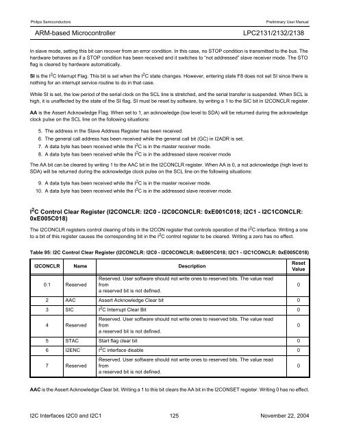
I 2 C Control Clear Register (I2CONCLR: I2C0 - I2C0CONCLR: 0xE001C018; I2C1 - I2C1CONCLR:<br />
0xE005C018)<br />
The I2CONCLR registers control clearing of bits in the I2CON register that controls operation of the I 2 C interface. Writing a one<br />
to a bit of this register causes the corresponding bit in the I 2 C control register to be cleared. Writing a zero has no effect.<br />
Table 95: I2C Control Clear Register (I2CONCLR: I2C0 - I2C0CONCLR: 0xE001C018; I2C1 - I2C1CONCLR: 0xE005C018)<br />
I2CONCLR Name Description<br />
0:1 Reserved<br />
Reserved. <strong>User</strong> software should not write ones to reserved bits. The value read<br />
from<br />
a reserved bit is not defined.<br />
2 AAC Assert Acknowledge Clear bit 0<br />
3 SIC I 2 C Interrupt Clear Bit 0<br />
4 Reserved<br />
Reserved. <strong>User</strong> software should not write ones to reserved bits. The value read<br />
from<br />
a reserved bit is not defined.<br />
5 STAC Start flag clear bit 0<br />
6 I2ENC I 2 C interface disable 0<br />
7 Reserved<br />
Reserved. <strong>User</strong> software should not write ones to reserved bits. The value read<br />
from<br />
a reserved bit is not defined.<br />
Reset<br />
Value<br />
AAC is the Assert Acknowledge Clear bit. Writing a 1 to this bit clears the AA bit in the I2CONSET register. Writing 0 has no effect.<br />
I2C Interfaces I2C0 and I2C1 125 November 22, 2004<br />
0<br />
0<br />
0


