


Create successful ePaper yourself
Turn your PDF publications into a flip-book with our unique Google optimized e-Paper software.
Philips Semiconductors Preliminary <strong>User</strong> <strong>Manual</strong><br />
ARM-based Microcontroller<br />
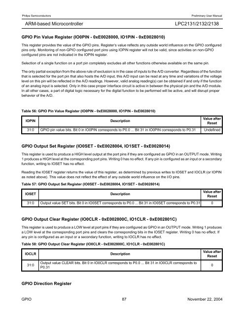
GPIO Pin Value Register (IO0PIN - 0xE0028000, IO1PIN - 0xE0028010)<br />
<strong>LPC2131</strong>/<strong>2132</strong>/<strong>2138</strong><br />
This register provides the value of the GPIO pins. Register’s value reflects any outside world influence on the GPIO configured<br />
pins only. Monitoring of non-GPIO configured port pins using IOPIN register will not be valid, since activities on non-GPIO<br />
configured pins are not indicated in the IOPIN register.<br />
Selection of a single function on a port pin completely excludes all other functions otherwise available on the same pin.<br />
The only partial exception from the above rule of exclusion is in the case of inputs to the A/D converter. Regardless of the function<br />
that is selected for the port pin that also hosts the A/D input, this A/D input can be read at any time and variations of the voltage<br />
level on this pin will be reflected in the A/D readings. However, valid analog reading(s) can be obtained if and only if the function<br />
of an analog input is selected. Only in this case proper interface circuit is active in between the physical pin and the A/D module.<br />
In all other cases, a part of digital logic necessary for the digital function to be performed will be active, and will disrupt proper<br />
behavior of the A/D.<br />
Table 56: GPIO Pin Value Register (IO0PIN - 0xE0028000, IO1PIN - 0xE0028010)<br />
IOPIN Description<br />
GPIO Output Set Register (IO0SET - 0xE0028004, IO1SET - 0xE0028014)<br />
This register is used to produce a HIGH level output at the port pins if they are configured as GPIO in an OUTPUT mode. Writing<br />
1 produces a HIGH level at the corresponding port pins. Writing 0 has no effect. If any pin is configured as an input or a secondary<br />
function, writing to IOSET has no effect.<br />
Reading the IOSET register returns the value of this register, as determined by previous writes to IOSET and IOCLR (or IOPIN<br />
as noted above). This value does not reflect the effect of any outside world influence on the I/O pins.<br />
GPIO Output Clear Register (IO0CLR - 0xE002800C, IO1CLR - 0xE002801C)<br />
This register is used to produce a LOW level at port pins if they are configured as GPIO in an OUTPUT mode. Writing 1 produces<br />
a LOW level at the corresponding port pins and clears the corresponding bits in the IOSET register. Writing 0 has no effect. If<br />
any pin is configured as an input or a secondary function, writing to IOCLR has no effect.<br />
GPIO Direction Register<br />
Value after<br />
Reset<br />
31:0 GPIO pin value bits. Bit 0 in IO0PIN corresponds to P0.0 ... Bit 31 in IO0PIN corresponds to P0.31 Undefined<br />
Table 57: GPIO Output Set Register (IO0SET - 0xE0028004, IO1SET - 0xE0028014)<br />
IOSET Description<br />
Value after<br />
Reset<br />
31:0 Output value SET bits. Bit 0 in IO0SET corresponds to P0.0 ... Bit 31 in IO0SET corresponds to P0.31 0<br />
Table 58: GPIO Output Clear Register (IO0CLR - 0xE002800C, IO1CLR - 0xE002801C)<br />
IOCLR Description<br />
31:0<br />
Output value CLEAR bits. Bit 0 in IO0CLR corresponds to P0.0 ... Bit 31 in IO0CLR corresponds to<br />
P0.31<br />
Value after<br />
Reset<br />
GPIO 87 November 22, 2004<br />
0


