


Create successful ePaper yourself
Turn your PDF publications into a flip-book with our unique Google optimized e-Paper software.
Philips Semiconductors Preliminary <strong>User</strong> <strong>Manual</strong><br />
ARM-based Microcontroller<br />
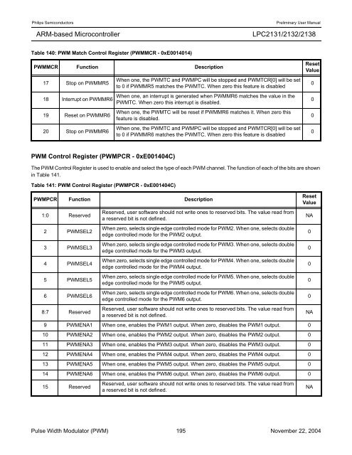
Table 140: PWM Match Control Register (PWMMCR - 0xE0014014)<br />
PWMMCR Function Description<br />
17 Stop on PWMMR5<br />
18 Interrupt on PWMMR6<br />
19 Reset on PWMMR6<br />
20 Stop on PWMMR6<br />
PWM Control Register (PWMPCR - 0xE001404C)<br />
<strong>LPC2131</strong>/<strong>2132</strong>/<strong>2138</strong><br />
When one, the PWMTC and PWMPC will be stopped and PWMTCR[0] will be set<br />
to 0 if PWMMR5 matches the PWMTC. When zero this feature is disabled<br />
When one, an interrupt is generated when PWMMR6 matches the value in the<br />
PWMTC. When zero this interrupt is disabled.<br />
When one, the PWMTC will be reset if PWMMR6 matches it. When zero this<br />
feature is disabled.<br />
When one, the PWMTC and PWMPC will be stopped and PWMTCR[0] will be set<br />
to 0 if PWMMR6 matches the PWMTC. When zero this feature is disabled<br />
The PWM Control Register is used to enable and select the type of each PWM channel. The function of each of the bits are shown<br />
in Table 141.<br />
Table 141: PWM Control Register (PWMPCR - 0xE001404C)<br />
PWMPCR Function Description<br />
1:0 Reserved<br />
2 PWMSEL2<br />
3 PWMSEL3<br />
4 PWMSEL4<br />
5 PWMSEL5<br />
6 PWMSEL6<br />
Reserved, user software should not write ones to reserved bits. The value read from<br />
a reserved bit is not defined.<br />
When zero, selects single edge controlled mode for PWM2. When one, selects double<br />
edge controlled mode for the PWM2 output.<br />
When zero, selects single edge controlled mode for PWM3. When one, selects double<br />
edge controlled mode for the PWM3 output.<br />
When zero, selects single edge controlled mode for PWM4. When one, selects double<br />
edge controlled mode for the PWM4 output.<br />
When zero, selects single edge controlled mode for PWM5. When one, selects double<br />
edge controlled mode for the PWM5 output.<br />
When zero, selects single edge controlled mode for PWM6. When one, selects double<br />
edge controlled mode for the PWM6 output.<br />
8:7 Reserved<br />
Reserved, user software should not write ones to reserved bits. The value read from<br />
a reserved bit is not defined.<br />
NA<br />
9 PWMENA1 When one, enables the PWM1 output. When zero, disables the PWM1 output. 0<br />
10 PWMENA2 When one, enables the PWM2 output. When zero, disables the PWM2 output. 0<br />
11 PWMENA3 When one, enables the PWM3 output. When zero, disables the PWM3 output. 0<br />
12 PWMENA4 When one, enables the PWM4 output. When zero, disables the PWM4 output. 0<br />
13 PWMENA5 When one, enables the PWM5 output. When zero, disables the PWM5 output. 0<br />
14 PWMENA6 When one, enables the PWM6 output. When zero, disables the PWM6 output. 0<br />
15 Reserved<br />
Reserved, user software should not write ones to reserved bits. The value read from<br />
a reserved bit is not defined.<br />
Reset<br />
Value<br />
Pulse Width Modulator (PWM) 195 November 22, 2004<br />
0<br />
0<br />
0<br />
0<br />
Reset<br />
Value<br />
NA<br />
0<br />
0<br />
0<br />
0<br />
0<br />
NA


