


You also want an ePaper? Increase the reach of your titles
YUMPU automatically turns print PDFs into web optimized ePapers that Google loves.
Philips Semiconductors Preliminary <strong>User</strong> <strong>Manual</strong><br />
ARM-based Microcontroller<br />
DETAILS OF I 2 C OPERATING MODES<br />
The four operating modes are:<br />
Master Transmitter.<br />
Master Receiver.<br />
Slave Receiver.<br />
Slave Transmitter.<br />
<strong>LPC2131</strong>/<strong>2132</strong>/<strong>2138</strong><br />
Data transfers in each mode of operation are shown in Figures 29 – 33. These figures contain the following abbreviations:<br />
Abbreviation Explanation<br />
S Start condition<br />
SLA 7-bit slave address<br />
R Read bit (high level at SDA)<br />
W Write bit (low level at SDA)<br />
A Acknowledge bit (low level at SDA)<br />
/A Not acknowledge bit (high level at SDA)<br />
Data 8-bit data byte<br />
P Stop condition<br />
In Figures 29 – 33, circles are used to indicate when the serial interrupt flag is set. The numbers in the circles show the status<br />
code held in the I2STAT register. At these points, a service routine must be executed to continue or complete the serial transfer.<br />
These service routines are not critical since the serial transfer is suspended until the serial interrupt flag is cleared by software.<br />
When a serial interrupt routine is entered, the status code in I2STAT is used to branch to the appropriate service routine. For<br />
each status code, the required software action and details of the following serial transfer are given in Tables 102-106.<br />
Master Transmitter Mode<br />
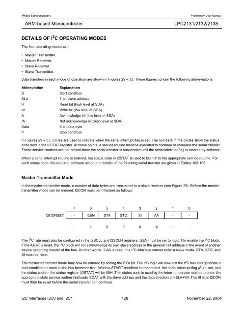
In the master transmitter mode, a number of data bytes are transmitted to a slave receiver (see Figure 29). Before the master<br />
transmitter mode can be entered, I2CON must be initialized as follows:<br />
7 6 5 4<br />
3 2 1 0<br />
I2CONSET - I2EN STA STO SI AA - -<br />
- 1 0 0 0 X - -<br />
The I 2 C rate must also be configured in the I2SCLL and I2SCLH registers. I2EN must be set to logic 1 to enable the I 2 C block.<br />
If the AA bit is reset, the I 2 C block will not acknowledge its own slave address or the general call address in the event of another<br />
device becoming master of the bus. In other words, if AA is reset, the I 2 C interface cannot enter a slave mode. STA, STO, and<br />
SI must be reset.<br />
The master transmitter mode may now be entered by setting the STA bit. The I 2 C logic will now test the I 2 C bus and generate a<br />
start condition as soon as the bus becomes free. When a START condition is transmitted, the serial interrupt flag (SI) is set, and<br />
the status code in the status register (I2STAT) will be 08H. This status code is used by the interrupt service routine to enter the<br />
appropriate state service routine that loads I2DAT with the slave address and the data direction bit (SLA+W). The SI bit in I2CON<br />
must then be reset before the serial transfer can continue.<br />
I2C Interfaces I2C0 and I2C1 128 November 22, 2004


