


Create successful ePaper yourself
Turn your PDF publications into a flip-book with our unique Google optimized e-Paper software.
Philips Semiconductors Preliminary <strong>User</strong> <strong>Manual</strong><br />
ARM-based Microcontroller<br />
<strong>LPC2131</strong>/<strong>2132</strong>/<strong>2138</strong><br />
10 characters, the CPU would receive 10 RDA interrupts resulting in the transfer of 100 characters and 1 to 5 CTI interrupts<br />
(depending on the service routine) resulting in the transfer of the remaining 5 characters.<br />
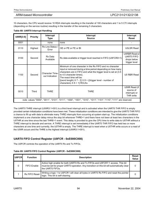
Table 68: UART0 Interrupt Handling<br />
U0IIR[3:0] Priority<br />
Interrupt<br />
Type<br />
The UART0 THRE interrupt (U0IIR3:1=001) is a third level interrupt and is activated when the UART0 THR FIFO is empty<br />
provided certain initialization conditions have been met. These initialization conditions are intended to give the UART0 THR FIFO<br />
a chance to fill up with data to eliminate many THRE interrupts from occurring at system start-up. The initialization conditions<br />
implement a one character delay minus the stop bit whenever THRE=1 and there have not been at least two characters in the<br />
U0THR at one time since the last THRE=1 event. This delay is provided to give the CPU time to write data to U0THR without a<br />
THRE interrupt to decode and service. A THRE interrupt is set immediately if the UART0 THR FIFO has held two or more<br />
characters at one time and currently, the U0THR is empty. The THRE interrupt is reset when a U0THR write occurs or a read of<br />
the U0IIR occurs and the THRE is the highest interrupt (U0IIR3:1=001).<br />
UART0 FIFO Control Register (U0FCR - 0xE000C008)<br />
The U0FCR controls the operation of the UART0 Rx and Tx FIFOs.<br />
Interrupt<br />
Source<br />
0001 - none none -<br />
0110 Highest<br />
0100 Second<br />
1100 Second<br />
Rx Line Status /<br />
Error<br />
Rx Data<br />
Available<br />
Character Timeout<br />
Indication<br />
Interrupt<br />
Reset<br />
OE or PE or FE or BI U0LSR Read<br />
Rx data available or trigger level reached in FIFO (U0FCR0=1)<br />
Minimum of one character in the Rx FIFO and no character<br />
input or removed during a time period depending on how many<br />
characters are in FIFO and what the trigger level is set at (3.5<br />
to 4.5 character times).<br />
The exact time will be:<br />
[(word length) X 7 - 2] X 8 + {(trigger level - number of<br />
characters) X 8 + 1] RCLKs<br />
0010 Third THRE THRE<br />
U0RBR Read or<br />
UART0 FIFO<br />
drops below<br />
trigger level<br />
U0 RBR Read<br />
U0IIR Read (if<br />
source of<br />
interrupt) or<br />
THR write<br />
note: values "0000", “0011”, “0101”, “0111”, “1000”, “1001”, “1010”, “1011”,”1101”,”1110”,”1111” are reserved.<br />
Table 69: UART0 FIFO Control Register (U0FCR - 0xE000C008)<br />
U0FCR Function Description<br />
0 FIFO Enable<br />
1 Rx FIFO Reset<br />
Active high enable for both UART0 Rx and Tx FIFOs and U0FCR7:1 access. This bit<br />
must be set for proper UART0 operation. Any transition on this bit will automatically clear<br />
the UART0 FIFOs.<br />
Writing a logic 1 to U0FCR1 will clear all bytes in UART0 Rx FIFO and reset the pointer<br />
logic. This bit is self-clearing.<br />
Reset<br />
Value<br />
UART0 94 November 22, 2004<br />
0<br />
0


