


You also want an ePaper? Increase the reach of your titles
YUMPU automatically turns print PDFs into web optimized ePapers that Google loves.
Philips Semiconductors Preliminary <strong>User</strong> <strong>Manual</strong><br />
ARM-based Microcontroller<br />
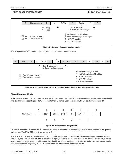
Figure 21: Format of master receiver mode<br />
After a repeated START condition, I 2 C may switch to the master transmitter mode.<br />
Slave Receiver Mode:<br />
S Slave Address R A DATA A DATA A P<br />
From Master to Slave<br />
From Slave to Master<br />
"0" - Write<br />
"1" - Read<br />
Figure 22: A master receiver switch to master transmitter after sending repeated START<br />
<strong>LPC2131</strong>/<strong>2132</strong>/<strong>2138</strong><br />
In the slave receiver mode, data bytes are received from a master transmitter. To initialize the slave receiver mode, user should<br />
write the Slave Address Register (I2ADR) and write the I 2 C Control Set Register (I2CONSET) as shown in Figure 23.<br />
Figure 23: Slave Mode Configuration<br />
Data Transferred<br />
(n Bytes + Acknowledge)<br />
A = Acknowledge (SDA low)<br />
A = Not Acknowledge (SDA high)<br />
S = START condition<br />
P = STOP Condition<br />
S SLA R A DATA A DATA A RS SLA W A DATA A<br />
From Master to Slave<br />
From Slave to Master<br />
Data Transferred<br />
(n Bytes + Acknowledge)<br />
A = Acknowledge (SDA low)<br />
A = Not Acknowledge (SDA high)<br />
S = START condition<br />
P = STOP Condition<br />
SLA = Slave Address<br />
7 6 5 4 3 2 1 0<br />
I2CONSET - I2EN STA STO SI AA - -<br />
- 1 0 0 0 1 - -<br />
I2EN must be set to 1 to enable the I 2 C function. AA bit must be set to 1 to acknowledge its own slave address or the general<br />
call address. The STA, STO and SI bits are set to 0.<br />
After I2ADR and I2CONSET are initialized, the I 2 C interface waits until it is addressed by its own address or general address<br />
followed by the data direction bit. If the direction bit is 0 (W), it enters slave receiver mode. If the direction bit is 1 (R), it enters<br />
slave transmitter mode. After the address and direction bit have been received, the SI bit is set and a valid status code can be<br />
read from the Status Register (I2STAT). Refer to Table 104 for the status codes and actions.<br />
I2C Interfaces I2C0 and I2C1 118 November 22, 2004<br />
P


