


Create successful ePaper yourself
Turn your PDF publications into a flip-book with our unique Google optimized e-Paper software.
Philips Semiconductors Preliminary <strong>User</strong> <strong>Manual</strong><br />
ARM-based Microcontroller<br />
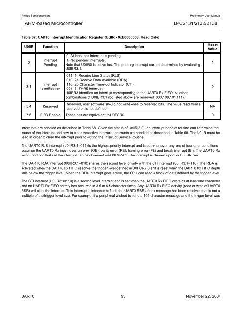
Table 67: UART0 Interrupt Identification Register (U0IIR - 0xE000C008, Read Only)<br />
U0IIR Function Description<br />
0<br />
3:1<br />
Interrupt<br />
Pending<br />
Interrupt<br />
Identification<br />
<strong>LPC2131</strong>/<strong>2132</strong>/<strong>2138</strong><br />
0: At least one interrupt is pending.<br />
1: No pending interrupts.<br />
Note that U0IIR0 is active low. The pending interrupt can be determined by evaluating<br />
U0IER3:1.<br />
011: 1. Receive Line Status (RLS)<br />
010: 2a.Receive Data Available (RDA)<br />
110: 2b.Character Time-out Indicator (CTI)<br />
001: 3. THRE Interrupt.<br />
U0IER3 identifies an interrupt corresponding to the UART0 Rx FIFO. All other<br />
combinations of U0IER3:1 not listed above are reserved (000,100,101,111).<br />
5:4 Reserved<br />
Reserved, user software should not write ones to reserved bits. The value read from a<br />
reserved bit is not defined.<br />
NA<br />
7:6 FIFO Enable These bits are equivalent to U0FCR0. 0<br />
Reset<br />
Value<br />
Interrupts are handled as described in Table 68. Given the status of U0IIR[3:0], an interrupt handler routine can determine the<br />
cause of the interrupt and how to clear the active interrupt. Interrupts are handled as described in Table 68. The U0IIR must be<br />
read in order to clear the interrupt prior to exiting the Interrupt Service Routine.<br />
The UART0 RLS interrupt (U0IIR3:1=011) is the highest priority interrupt and is set whenever any one of four error conditions<br />
occur on the UART0 Rx input: overrun error (OE), parity error (PE), framing error (FE) and break interrupt (BI). The UART0 Rx<br />
error condition that set the interrupt can be observed via U0LSR4:1. The interrupt is cleared upon an U0LSR read.<br />
The UART0 RDA interrupt (U0IIR3:1=010) shares the second level priority with the CTI interrupt (U0IIR3:1=110). The RDA is<br />
activated when the UART0 Rx FIFO reaches the trigger level defined in U0FCR7:6 and is reset when the UART0 Rx FIFO depth<br />
falls below the trigger level. When the RDA interrupt goes active, the CPU can read a block of data defined by the trigger level.<br />
The CTI interrupt (U0IIR3:1=110) is a second level interrupt and is set when the UART0 Rx FIFO contains at least one character<br />
and no UART0 Rx FIFO activity has occurred in 3.5 to 4.5 character times. Any UART0 Rx FIFO activity (read or write of UART0<br />
RSR) will clear the interrupt. This interrupt is intended to flush the UART0 RBR after a message has been received that is not a<br />
multiple of the trigger level size. For example, if a peripheral wished to send a 105 character message and the trigger level was<br />
UART0 93 November 22, 2004<br />
1<br />
0


