


Create successful ePaper yourself
Turn your PDF publications into a flip-book with our unique Google optimized e-Paper software.
Philips Semiconductors Preliminary <strong>User</strong> <strong>Manual</strong><br />
ARM-based Microcontroller<br />
MAM Control Register (MAMCR - 0xE01FC000)<br />
<strong>LPC2131</strong>/<strong>2132</strong>/<strong>2138</strong><br />
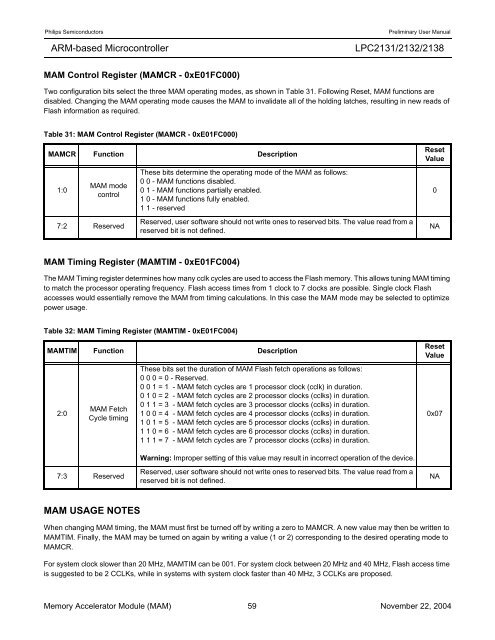
Two configuration bits select the three MAM operating modes, as shown in Table 31. Following Reset, MAM functions are<br />
disabled. Changing the MAM operating mode causes the MAM to invalidate all of the holding latches, resulting in new reads of<br />
Flash information as required.<br />
Table 31: MAM Control Register (MAMCR - 0xE01FC000)<br />
MAMCR Function Description<br />
1:0<br />
MAM mode<br />
control<br />
7:2 Reserved<br />
MAM Timing Register (MAMTIM - 0xE01FC004)<br />
The MAM Timing register determines how many cclk cycles are used to access the Flash memory. This allows tuning MAM timing<br />
to match the processor operating frequency. Flash access times from 1 clock to 7 clocks are possible. Single clock Flash<br />
accesses would essentially remove the MAM from timing calculations. In this case the MAM mode may be selected to optimize<br />
power usage.<br />
MAM USAGE NOTES<br />
These bits determine the operating mode of the MAM as follows:<br />
0 0 - MAM functions disabled.<br />
0 1 - MAM functions partially enabled.<br />
1 0 - MAM functions fully enabled.<br />
1 1 - reserved<br />
Reserved, user software should not write ones to reserved bits. The value read from a<br />
reserved bit is not defined.<br />
Table 32: MAM Timing Register (MAMTIM - 0xE01FC004)<br />
MAMTIM Function Description<br />
2:0<br />
MAM Fetch<br />
Cycle timing<br />
7:3 Reserved<br />
These bits set the duration of MAM Flash fetch operations as follows:<br />
0 0 0 = 0 - Reserved.<br />
0 0 1 = 1 - MAM fetch cycles are 1 processor clock (cclk) in duration.<br />
0 1 0 = 2 - MAM fetch cycles are 2 processor clocks (cclks) in duration.<br />
0 1 1 = 3 - MAM fetch cycles are 3 processor clocks (cclks) in duration.<br />
1 0 0 = 4 - MAM fetch cycles are 4 processor clocks (cclks) in duration.<br />
1 0 1 = 5 - MAM fetch cycles are 5 processor clocks (cclks) in duration.<br />
1 1 0 = 6 - MAM fetch cycles are 6 processor clocks (cclks) in duration.<br />
1 1 1 = 7 - MAM fetch cycles are 7 processor clocks (cclks) in duration.<br />
Warning: Improper setting of this value may result in incorrect operation of the device.<br />
Reserved, user software should not write ones to reserved bits. The value read from a<br />
reserved bit is not defined.<br />
Reset<br />
Value<br />
When changing MAM timing, the MAM must first be turned off by writing a zero to MAMCR. A new value may then be written to<br />
MAMTIM. Finally, the MAM may be turned on again by writing a value (1 or 2) corresponding to the desired operating mode to<br />
MAMCR.<br />
For system clock slower than 20 MHz, MAMTIM can be 001. For system clock between 20 MHz and 40 MHz, Flash access time<br />
is suggested to be 2 CCLKs, while in systems with system clock faster than 40 MHz, 3 CCLKs are proposed.<br />
Memory Accelerator Module (MAM) 59 November 22, 2004<br />
0<br />
NA<br />
Reset<br />
Value<br />
0x07<br />
NA


