


Create successful ePaper yourself
Turn your PDF publications into a flip-book with our unique Google optimized e-Paper software.
Philips Semiconductors Preliminary <strong>User</strong> <strong>Manual</strong><br />
ARM-based Microcontroller<br />
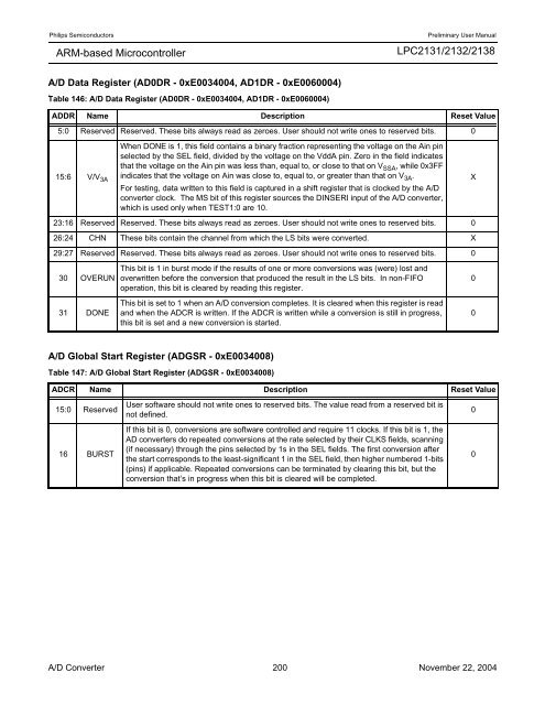
A/D Data Register (AD0DR - 0xE0034004, AD1DR - 0xE0060004)<br />
.<br />
Table 146: A/D Data Register (AD0DR - 0xE0034004, AD1DR - 0xE0060004)<br />
A/D Global Start Register (ADGSR - 0xE0034008)<br />
<strong>LPC2131</strong>/<strong>2132</strong>/<strong>2138</strong><br />
ADDR Name Description Reset Value<br />
5:0 Reserved Reserved. These bits always read as zeroes. <strong>User</strong> should not write ones to reserved bits. 0<br />
15:6 V/V 3A<br />
When DONE is 1, this field contains a binary fraction representing the voltage on the Ain pin<br />
selected by the SEL field, divided by the voltage on the VddA pin. Zero in the field indicates<br />
that the voltage on the Ain pin was less than, equal to, or close to that on VSSA , while 0x3FF<br />
indicates that the voltage on Ain was close to, equal to, or greater than that on V3A .<br />
For testing, data written to this field is captured in a shift register that is clocked by the A/D<br />
converter clock. The MS bit of this register sources the DINSERI input of the A/D converter,<br />
which is used only when TEST1:0 are 10.<br />
23:16 Reserved Reserved. These bits always read as zeroes. <strong>User</strong> should not write ones to reserved bits. 0<br />
26:24 CHN These bits contain the channel from which the LS bits were converted. X<br />
29:27 Reserved Reserved. These bits always read as zeroes. <strong>User</strong> should not write ones to reserved bits. 0<br />
30 OVERUN<br />
31 DONE<br />
This bit is 1 in burst mode if the results of one or more conversions was (were) lost and<br />
overwritten before the conversion that produced the result in the LS bits. In non-FIFO<br />
operation, this bit is cleared by reading this register.<br />
This bit is set to 1 when an A/D conversion completes. It is cleared when this register is read<br />
and when the ADCR is written. If the ADCR is written while a conversion is still in progress,<br />
this bit is set and a new conversion is started.<br />
Table 147: A/D Global Start Register (ADGSR - 0xE0034008)<br />
ADCR Name Description Reset Value<br />
15:0 Reserved<br />
16 BURST<br />
<strong>User</strong> software should not write ones to reserved bits. The value read from a reserved bit is<br />
not defined.<br />
If this bit is 0, conversions are software controlled and require 11 clocks. If this bit is 1, the<br />
AD converters do repeated conversions at the rate selected by their CLKS fields, scanning<br />
(if necessary) through the pins selected by 1s in the SEL fields. The first conversion after<br />
the start corresponds to the least-significant 1 in the SEL field, then higher numbered 1-bits<br />
(pins) if applicable. Repeated conversions can be terminated by clearing this bit, but the<br />
conversion that’s in progress when this bit is cleared will be completed.<br />
A/D Converter 200 November 22, 2004<br />
X<br />
0<br />
0<br />
0<br />
0


