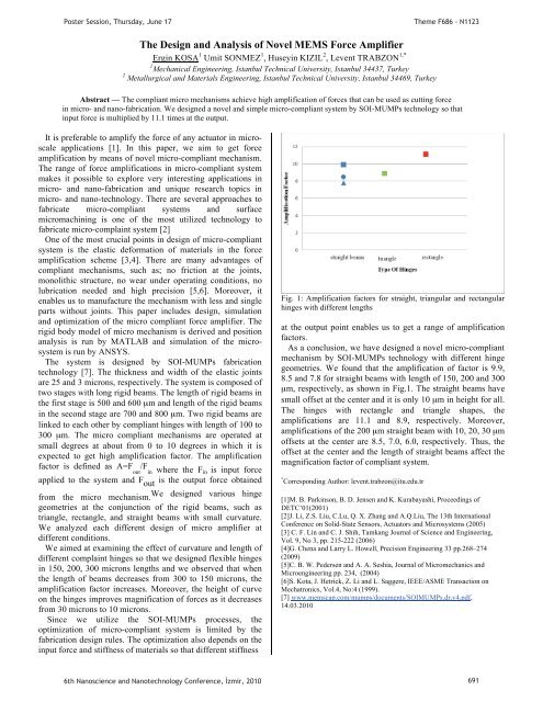
Poster Session, Thursday, June 17Theme F686 - N1123The Design and Analysis of Novel MEMS Force AmplifierErg<strong>in</strong> KOSA 1 Umit SONMEZ 1 , Husey<strong>in</strong> KIZIL 2 , Levent TRABZON 1,*1 Mechanical Eng<strong>in</strong>eer<strong>in</strong>g, Istanbul Technical University, Istanbul 34437, Turkey2 Metallurgical and Materials Eng<strong>in</strong>eer<strong>in</strong>g, Istanbul Technical University, Istanbul 34469, TurkeyAbstract — The compliant micro mechanisms achieve high amplification of forces that can be used as cutt<strong>in</strong>g force<strong>in</strong> micro- and nano-fabrication. We designed a novel and simple micro-compliant system by SOI-MUMPs technology so that<strong>in</strong>put force is multiplied by 11.1 times at the output.It is preferable to amplify the force of any actuator <strong>in</strong> microscaleapplications [1]. In this paper, we aim to get forceamplification by means of novel micro-compliant mechanism.The range of force amplifications <strong>in</strong> micro-compliant systemmakes it possible to explore very <strong>in</strong>terest<strong>in</strong>g applications <strong>in</strong>micro- and nano-fabrication and unique research topics <strong>in</strong>micro- and nano-technology. There are several approaches tofabricate micro-compliant systems and surfacemicromach<strong>in</strong><strong>in</strong>g is one of the most utilized technology tofabricate micro-compla<strong>in</strong>t system [2]One of the most crucial po<strong>in</strong>ts <strong>in</strong> design of micro-compliantsystem is the elastic deformation of materials <strong>in</strong> the forceamplification scheme [3,4]. There are many advantages ofcompliant mechanisms, such as; no friction at the jo<strong>in</strong>ts,monolithic structure, no wear under operat<strong>in</strong>g conditions, nolubrication needed and high precision [5,6]. Moreover, itenables us to manufacture the mechanism with less and s<strong>in</strong>gleparts without jo<strong>in</strong>ts. This paper <strong>in</strong>cludes design, simulationand optimization of the micro compliant force amplifier. Therigid body model of micro mechanism is derived and positionanalysis is run by MATLAB and simulation of the microsystemis run by ANSYS.The system is designed by SOI-MUMPs fabricationtechnology [7]. The thickness and width of the elastic jo<strong>in</strong>tsare 25 and 3 microns, respectively. The system is composed oftwo stages with long rigid beams. The length of rigid beams <strong>in</strong>the first stage is 500 and 600 μm and length of the rigid beams<strong>in</strong> the second stage are 700 and 800 μm. Two rigid beams arel<strong>in</strong>ked to each other by compliant h<strong>in</strong>ges with length of 100 to300 μm. The micro compliant mechanisms are operated atsmall degrees at about from 0 to 10 degrees <strong>in</strong> which it isexpected to get high amplification factor. The amplificationfactor is def<strong>in</strong>ed as A=F /Fout <strong>in</strong> where the F <strong>in</strong> is <strong>in</strong>put forceapplied to the system and F out is the output force obta<strong>in</strong>edfrom the micro mechanism.We designed various h<strong>in</strong>gegeometries at the conjunction of the rigid beams, such astriangle, rectangle, and straight beams with small curvature.We analyzed each different design of micro amplifier atdifferent conditions.We aimed at exam<strong>in</strong><strong>in</strong>g the effect of curvature and length ofdifferent compla<strong>in</strong>t h<strong>in</strong>ges so that we designed flexible h<strong>in</strong>ges<strong>in</strong> 150, 200, 300 microns lengths and we observed that whenthe length of beams decreases from 300 to 150 microns, theamplification factor <strong>in</strong>creases. Moreover, the height of curveon the h<strong>in</strong>ges improves magnification of forces as it decreasesfrom 30 microns to 10 microns.S<strong>in</strong>ce we utilize the SOI-MUMPs processes, theoptimization of micro-compliant system is limited by thefabrication design rules. The optimization also depends on the<strong>in</strong>put force and stiffness of materials so that different stiffnessFig. 1: Amplification factors for straight, triangular and rectangularh<strong>in</strong>ges with different lengthsat the output po<strong>in</strong>t enables us to get a range of amplificationfactors.As a conclusion, we have designed a novel micro-compliantmechanism by SOI-MUMPs technology with different h<strong>in</strong>gegeometries. We found that the amplification of factor is 9.9,8.5 and 7.8 for straight beams with length of 150, 200 and 300μm, respectively, as shown <strong>in</strong> Fig.1. The straight beams havesmall offset at the center and it is only 10 μm <strong>in</strong> height for all.The h<strong>in</strong>ges with rectangle and triangle shapes, theamplifications are 11.1 and 8.9, respectively. Moreover,amplifications of the 200 μm straight beam with 10, 20, 30 μmoffsets at the center are 8.5, 7.0, 6.0, respectively. Thus, theoffset at the center and the length of straight beams affect themagnification factor of compliant system.* Correspond<strong>in</strong>g Author: levent.trabzon@itu.edu.tr[1]M. B. Park<strong>in</strong>son, B. D. Jensen and K. Kurabayashi, Proceed<strong>in</strong>gs ofDETC’01(2001)[2]J. Li, Z.S. Liu, C.Lu, Q. X. Zhang and A.Q.Liu, The 13th InternationalConference on Solid-State Sensors, Actuators and Microsystems (2005)[3] C. F. L<strong>in</strong> and C. J. Shih, Tamkang Journal of Science and Eng<strong>in</strong>eer<strong>in</strong>g,Vol. 9, No 3, pp. 215-222 (2006)[4]G. Chena and Larry L. Howell, Precision Eng<strong>in</strong>eer<strong>in</strong>g 33 pp.268–274(2009)[5]C. B. W. Pedersen and A. A. Seshia, Journal of Micromechanics andMicroeng<strong>in</strong>eer<strong>in</strong>g pp. 234, (2004)[6]S. Kota, J. Hetrick, Z. Li and L. Saggere, IEEE/ASME Transaction onMechatronics, Vol.4, No:4 (1999).[7] www.memscap.com/mumps/documents/SOIMUMPs.dr.v4.pdf,14.03.20106th Nanoscience and Nanotechnology Conference, zmir, 2010 691
PPoster Session, Thursday, June 17Theme F686 - N1123A New Model to Calculate Pull-<strong>in</strong> Limit and Position of Electrostatic Fixed-Fixed Beam Actuator11UCevher AkUP P* and Ali YildizP1PDepartment of Electrical-Electronics Eng<strong>in</strong>eer<strong>in</strong>g, Mers<strong>in</strong> University, Mers<strong>in</strong> 33342, TurkeyAbstract-This paper present a new formula and model that has been developed to calculate pull-<strong>in</strong> limit of fixed-fixed cantilever MEMSactuators. In the model, we both determ<strong>in</strong>ed a new pull-<strong>in</strong> limit and formulated the relationship between voltage and deflection. Formula is wellmatchedwith results of simulation that is based f<strong>in</strong>ite-element method.Electrostatic actuators have been very popular due to theirlow-power consumption, small dimensions, and easyfabrication. They have been used as a capacitive pressuresensor for measur<strong>in</strong>g blood pressure [1], as a microwaveswitch [2], as an air flow sensor [3], as a micro-actuator forprobe-based data storage [4], as an <strong>in</strong>kjet head [5], and opticalscanners [6] is well known commercial applications.An electrostatic MEMS actuators consist of a two parallelplate, one is coated on a substrate and not movable (bottomelectrode), the other one (top electrode) is above it with an<strong>in</strong>itial gap and fixed from both end. The middle of topelectrode is free to move. When a voltage difference is appliedbetween electrodes, middle of top electrode will <strong>in</strong>cl<strong>in</strong>e tobottom electrode (see Figure1).Figure 1. Bectrostaticactuator (Side wiew)For many years, researchers have used lumped model forelectrostatic MEMS actuators to calculate pull-<strong>in</strong> limit. It wasestimated as one-third of <strong>in</strong>itial gap. However, when it ischecked by software which utilizes f<strong>in</strong>ite element method,pull-<strong>in</strong> limit seems to be at a different value. It appears to bearound 40% of <strong>in</strong>itial gap (see Figure 2).and displacement. Values calculated from model are veryclose to those obta<strong>in</strong>ed from simulation. Model also delivers asimple formula. One can simply calculate required voltage fora desired displacement <strong>in</strong>stead of utiliz<strong>in</strong>g numericaldistributed methods which is time consum<strong>in</strong>g and requiresmore comput<strong>in</strong>g power.*Correspond<strong>in</strong>g author: cevher.ak@mers<strong>in</strong>.edu.tr[1] H<strong>in</strong>-Leung Chau, and K.D. Wise, “An ultram<strong>in</strong>iature solid-statepressure sensor for a cardiovascular catheter,” IEEE Trans. ElectronDevices, vol. 35(12), pp. 2355-2362, 1988.[2] Dooyoung Hah, and Euisik Yoon, “A Low-Voltage ActuatedMicromach<strong>in</strong>ed Microwave Switch Us<strong>in</strong>g Torsion Spr<strong>in</strong>gs andLeverage,” IEEE Trans. Microwave Theory and Tech., vol. 48(12),pp. 2540-2545, Dec. 2000.[3] Yu-Hsiang Wang, and Chia-Yen Lee, “A Mems-based Air FlowSensor with a Free-Stand<strong>in</strong>g Micro-cantilever Structure,” Sensors,vol. 7, pp. 2389-2401, Oct. 2007.[4] Michel S.C. Lu, and Gary K. Fedder, “Position Control ofParallel-Plate Microactuators for Probe-Based Data Storage,” J.Microelectromech. Syst., vol. 13(5), pp. 759-769, Oct. 2004. 9[5] S. Kamusuki, M. Fujii, T. Takekoshi, C. Tezuka, and M. Atobe,“A high resolution, electrostatically driven commercial <strong>in</strong>kjet head,”Proc. IEEE MEMS 2000 conf., pp. 793-798, Miyazaki, Japan, 23-27Jan. 2000.[6] H. Schenk, P. Dürr, D. Kunze, H. Lakner, and H. Kück, “Anelectrostatically excited 2D-micro scann<strong>in</strong>g-mirror with an <strong>in</strong> planeconfiguration of the driv<strong>in</strong>g electrodes,” Proc. IEEE MEMS 2000Conf., Miyazaki, Japan, 23-27 Jan. 2000, pp. 473-478.Figure 2. New modelIn this work, we proposed a new model which gives pull-<strong>in</strong>limit of a fixed-fixed beam actuator at 40% of the <strong>in</strong>itial gap.It is consistent with simulation results and previousexperimental models. In addition to pull-<strong>in</strong> limit, the newmodel demonstrates a good relation between applied voltage6th Nanoscience and Nanotechnology Conference, zmir, 2010 692
- Page 1:
Poster Presentations3rd Day17 June
- Page 4 and 5:
Determination of Dielectric Anisotr
- Page 7 and 8:
Poster Session, Thursday, June 17Th
- Page 9 and 10:
PP mPP vs.P =P,PP (1)P andPoster Se
- Page 11 and 12:
PP mPP vs.P =P,PP (1)P andPoster Se
- Page 13 and 14:
PP andPoster Session, Thursday, Jun
- Page 15 and 16:
Poster Session, Thursday, June 17Th
- Page 17 and 18:
PP and770 772 774 776 778 780 782 7
- Page 19 and 20:
Poster Session, Thursday, June 17Th
- Page 21 and 22:
Poster Session, Thursday, June 17Th
- Page 23 and 24:
P25,Poster Session, Thursday, June
- Page 25 and 26:
PP TOBBPoster Session, Thursday, Ju
- Page 27 and 28:
PisPPisisisP,PisPoster Session, Thu
- Page 29 and 30:
U NeslihanPPPPoster Session, Thursd
- Page 31 and 32: Poster Session, Thursday, June 17Th
- Page 33 and 34: PPPoster Session, Thursday, June 17
- Page 35 and 36: PPoster Session, Thursday, June 17T
- Page 37 and 38: P onP viaPP wereP upPoster Session,
- Page 39 and 40: P ·cm.PVPPPsPPPPP andPoster Sessio
- Page 41 and 42: Poster Session, Thursday, June 17Th
- Page 43 and 44: PPoster Session, Thursday, June 17T
- Page 45 and 46: PPoster Session, Thursday, June 17T
- Page 47 and 48: Poster Session, Thursday, June 17Th
- Page 49 and 50: PErkanPoster Session, Thursday, Jun
- Page 51 and 52: Poster Session, Thursday, June 17Th
- Page 53 and 54: Poster Session, Thursday, June 17Th
- Page 55 and 56: PPPP andPoster Session, Thursday, J
- Page 57 and 58: Poster Session, Thursday, June 17Th
- Page 59 and 60: Poster Session, Thursday, June 17Th
- Page 61 and 62: T PeptideTPP,PP,PP andTT2429TTTTTT
- Page 63 and 64: Poster Session, Thursday, June 17Th
- Page 65 and 66: PPoster Session, Thursday, June 17T
- Page 67 and 68: Poster Session, Thursday, June 17Th
- Page 69 and 70: PPPoster Session, Thursday, June 17
- Page 71 and 72: Poster Session, Thursday, June 17Th
- Page 73 and 74: Poster Session, Thursday, June 17Th
- Page 75 and 76: PT AdditionalT ThePoster Session, T
- Page 77 and 78: Poster Session, Thursday, June 17Th
- Page 79 and 80: Poster Session, Thursday, June 17Th
- Page 81: Poster Session, Thursday, June 17Th
- Page 85 and 86: Poster Session, Thursday, June 17Th
- Page 87 and 88: PPPoster Session, Thursday, June 17
- Page 89 and 90: Poster Session, Thursday, June 17Hu
- Page 91 and 92: Poster Session, Thursday, June 17Th
- Page 93 and 94: PPPPPPoster Session, Thursday, June
- Page 95 and 96: Poster Session, Thursday, June 17Th
- Page 97 and 98: Poster Session, Thursday, June 17Th
- Page 99 and 100: Poster Session, Thursday, June 17Th
- Page 101 and 102: PPoster Session, Thursday, June 17T
- Page 103 and 104: Poster Session, Thursday, June 17Th
- Page 105 and 106: PPPPPPPoster Session, Thursday, Jun
- Page 107 and 108: Poster Session, Thursday, June 17Th
- Page 109 and 110: PPPR2R PIN(80)PPgPP OzlemPPoster Se
- Page 111 and 112: Poster Session, Thursday, June 17Th
- Page 113 and 114: Poster Session, Thursday, June 17Th
- Page 115 and 116: P onPP toP coordinatedPPoster Sessi
- Page 117 and 118: PPPPP,PP,P(PR RmPoster Session, Thu
- Page 119 and 120: Poster Session, Thursday, June 17Th
- Page 121 and 122: Poster Session, Thursday, June 17Th
- Page 123 and 124: PP InstitutePP DepartmentPoster Ses
- Page 125 and 126: andPCPPoster Session, Thursday, Jun
- Page 127 and 128: PP scatteringPYusufPP Corresponding
- Page 129 and 130: PP toPoster Session, Thursday, June
- Page 131 and 132: PP andPoster Session, Thursday, Jun
- Page 133 and 134:
PPPPoster Session, Thursday, June 1
- Page 135 and 136:
PPoster Session, Thursday, June 17T
- Page 137 and 138:
PPP andP (.cm).Poster Session, Thur
- Page 139 and 140:
PP tiltP andP editionPoster Session
- Page 141 and 142:
PP andPPoster Session, Thursday, Ju
- Page 143 and 144:
Poster Session, Thursday, June 17Th
- Page 145 and 146:
PP forP forP edit.PPoster Session,
- Page 147 and 148:
Poster Session, Thursday, June 17Th
- Page 149 and 150:
Poster Session, Thursday, June 17Th
- Page 151 and 152:
PP ionicPP ,PPoster Session, Thursd
- Page 153 and 154:
PP lightPoster Session, Thursday, J
- Page 155 and 156:
Poster Session, Thursday, June 17Th
- Page 157 and 158:
PPoster Session, Thursday, June 17T
- Page 159 and 160:
Poster Session, Thursday, June 17Th
- Page 161 and 162:
PandPoster Session, Thursday, June
- Page 163 and 164:
Poster Session, Thursday, June 17 T
- Page 165 and 166:
PPPoster Session, Thursday, June 17
- Page 167 and 168:
PPoster Session, Thursday, June 17T
- Page 169 and 170:
PPoster Session, Thursday, June 17T
- Page 171 and 172:
PPoster Session, Thursday, June 17T
- Page 173 and 174:
PP DepartmentNanoscienceTPPoster Se
- Page 175 and 176:
Poster Session, Thursday, June 17Th
- Page 177 and 178:
Poster Session, Thursday, June 17Th
- Page 179 and 180:
PPPoster Session, Thursday, June 17
- Page 181 and 182:
PPPPPoster Session, Thursday, June
- Page 183 and 184:
PPPPoster Session, Thursday, June 1
- Page 185 and 186:
PPoster Session, Thursday, June 17T
- Page 187 and 188:
PPoster Session, Thursday, June 17T
- Page 189 and 190:
PPoster Session, Thursday, June 17T
- Page 191 and 192:
Poster Session, Thursday, June 17Th
- Page 193 and 194:
Poster Session, Thursday, June 17Th
- Page 195 and 196:
0T0T0T0T AsPPPP werePoster Session,
- Page 197 and 198:
PPoster Session, Thursday, June 17T
- Page 199 and 200:
PPPPPoster Session, Thursday, June
- Page 201 and 202:
PPoster Session, Thursday, June 17T
- Page 203 and 204:
PPoster Session, Thursday, June 17T
- Page 205 and 206:
Poster Session, Thursday, June 17Th
- Page 207 and 208:
PPoster Session, Thursday, June 17T
- Page 209 and 210:
PPoster Session, Thursday, June 17T
- Page 211:
Poster Session, Thursday, June 17AF