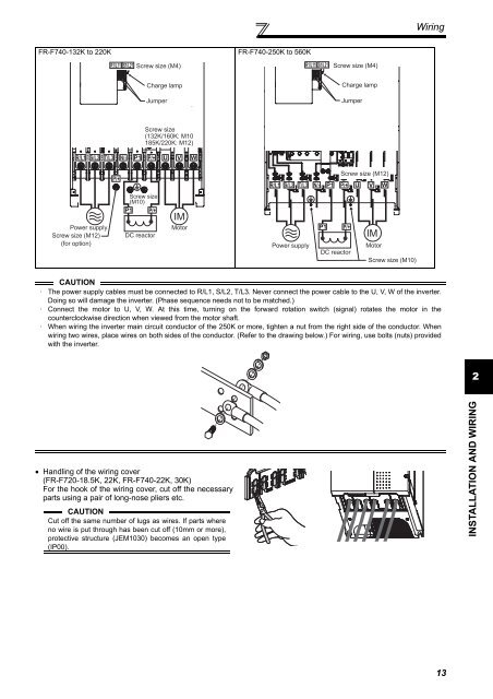
Wiring<strong>FR</strong>-F740-132K to 220KR1/L11 S1/L21 Screw size (M4)<strong>FR</strong>-F740-250K to 560KR1/L11 S1/L21Screw size (M4)Charge lampJumperCharge lampJumperScrew size(132K/160K: M10185K/220K: M12)R/L1 S/L2 T/L3 N/-P/+P/+R/L1 S/L2 T/L3 N/-Screw size (M12)P/+Screw size(M10)P/+IMPower supplyScrew size (M12)(for option)DC reactorMotorPower supplyP/+DC reactorIMMotorScrew size (M10)CAUTION· The power supply cables must be connected to R/L1, S/L2, T/L3. Never connect the power cable to the U, V, W of the inverter.Doing so will damage the inverter. (Phase sequence needs not to be matched.)· Connect the motor to U, V, W. At this time, turning on the forward rotation switch (signal) rotates the motor in thecounterclockwise direction when viewed from the motor shaft.· When wiring the inverter main circuit conductor of the 250K or more, tighten a nut from the right side of the conductor. Whenwiring two wires, place wires on both sides of the conductor. (Refer to the drawing below.) For wiring, use bolts (nuts) providedwith the inverter.2• Handling of the wiring cover(<strong>FR</strong>-F720-18.5K, 22K, <strong>FR</strong>-F740-22K, 30K)For the hook of the wiring cover, cut off the necessaryparts using a pair of long-nose pliers etc.CAUTIONCut off the same number of lugs as wires. If parts whereno wire is put through has been cut off (10mm or more),protective structure (JEM1030) becomes an open type(IP00).INSTALLATION AND WIRING13
Wiring(1) Cable sizes etc., of the main control circuit terminals and earth (ground) terminalsSelect the recommended cable size to ensure that a voltage drop will be 2% max.If the wiring distance is long between the inverter and motor, a main circuit cable voltage drop will cause the motortorque to decrease especially at the output of a low frequency.The following table indicates a selection example for the wiring length of 20m.200V class (when input power supply is 220V)Applicable InverterTypeTerminalScrewSize *4TighteningTorqueN·mCrimpingTerminalR/L1,S/L2,T/L3U, V, WCable SizesHIV, etc. (mm 2 ) *1 AWG/MCM *2 PVC, etc. (mm 2 ) *3R/L1,S/L2,T/L3U, V, WEarth(Ground)cableR/L1,S/L2,T/L3U, V, WR/L1,S/L2,T/L3U, V, WEarth(Ground)cable<strong>FR</strong>-F720-0.75K to2.2KM4 1.5 2-4 2-4 2 2 2 14 14 2.5 2.5 2.5<strong>FR</strong>-F720-3.7K M4 1.5 5.5-4 5.5-4 3.5 3.5 3.5 12 12 4 4 4<strong>FR</strong>-F720-5.5K M4 1.5 5.5-4 5.5-4 5.5 5.5 5.5 10 10 6 6 6<strong>FR</strong>-F720-7.5K M5 2.5 14-5 8-5 14 8 14 6 8 16 10 16<strong>FR</strong>-F720-11K M5 2.5 14-5 14-5 14 14 14 6 6 16 16 16<strong>FR</strong>-F720-15K M5 2.5 22-5 22-5 22 22 14 4 6 (*5) 25 25 16<strong>FR</strong>-F720-18.5K M6 4.4 38-6 38-6 38 38 22 2 2 35 35 25<strong>FR</strong>-F720-22K M8 (M6) 7.8 38-8 38-8 38 38 22 2 2 35 35 25<strong>FR</strong>-F720-30K M8 (M6) 7.8 60-8 60-8 60 60 38 1/0 1/0 50 50 25<strong>FR</strong>-F720-37K M8 (M6) 7.8 80-8 80-8 80 80 38 3/0 3/0 70 70 35<strong>FR</strong>-F720-45K M10 (M8) 14.7 100-10 100-10 100 100 60 4/0 4/0 95 95 50<strong>FR</strong>-F720-55K M10 (M8) 14.7 100-10 100-10 100 100 60 4/0 4/0 95 95 50<strong>FR</strong>-F720-75K M12 (M10) 24.5 150-12 150-12 125 125 38 MCM250 MCM250 ⎯ ⎯ ⎯<strong>FR</strong>-F720-90K M12 (M10) 24.5 150-12 150-12 150 150 38 2×4/0 2×4/0 ⎯ ⎯ ⎯<strong>FR</strong>-F720-110K M12 (M10) 24.5 100-12 100-12 2×100 2×100 38 2×4/0 2×4/0 ⎯ ⎯ ⎯*1 The cable size is that of the cable (HIV cable (600V class 2 vinyl-insulated cable) etc.) with continuous maximum permissible temperature of75°C. Assumes that the ambient temperature is 50°C or less and the wiring distance is 20m or less.*2 The recommended cable size is that of the cable (THHW cable) with continuous maximum permissible temperature of 75°C. Assumes that theambient temperature is 40°C or less and the wiring distance is 20m or less.(Selection example for use mainly in the United States.)*3 For the 15K or less, the recommended cable size is that of the cable (PVC cable) with continuous maximum permissible temperature of 70°C.Assumes that the ambient temperature is 40°C or less and the wiring distance is 20m or less.For the 18.5K or more, the recommended cable size is that of the cable (XLPE cable) with continuous maximum permissible temperature of90°C. Assumes that the ambient temperature is 40°C or less and wiring is performed in an enclosure.(Selection example for use mainly in Europe.)*4 The terminal screw size indicates the terminal size for R/L1, S/L2, T/L3, U, V, W, R1/L11, S1/L21, P/+, N/-, P1, and a screw for earthing(grounding).A screw for earthing (grounding) of the 7.5K, 11K is indicated in ( ).A screw for earthing (grounding) of the 22K or more is indicated in ( ).*5 When connecting the option unit to P/+, P1, N/-, use THHN cables for the option and terminals R/L1, S/L2, T/L3, U, V, W.14