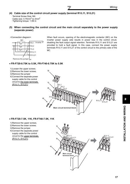
- Page 1 and 2: INVERTERINSTRUCTION MANUAL (BASIC)F
- Page 3 and 4: — CONTENTS —1 PRODUCT CHECKING
- Page 5 and 6: 6 PRECAUTIONS FOR MAINTENANCE AND I
- Page 7 and 8: 2 INSTALLATION AND WIRINGThree-phas
- Page 9 and 10: Peripheral devices400V classMotorOu
- Page 11 and 12: Method of removal and reinstallatio
- Page 13 and 14: Wiring2.4 Wiring2.4.1 Terminal conn
- Page 15 and 16: Wiring2.4.3 Specification of main c
- Page 17 and 18: Wiring400V classFR-F740-0.75K to 5.
- Page 19 and 20: Wiring(1) Cable sizes etc., of the
- Page 21: Wiring(2) Notes on earthing (ground
- Page 25 and 26: WiringTypeFrequency settingTerminal
- Page 27 and 28: Wiring2.4.6 Changing the control lo
- Page 29 and 30: Wiring2.4.7 Wiring of control circu
- Page 31 and 32: Wiring2.4.9 RS-485 terminal block
- Page 33 and 34: Precautions for use of the inverter
- Page 35 and 36: Failsafe of the system which uses t
- Page 37 and 38: Operation panel (FR-DU07)3.2 Operat
- Page 39 and 40: Operation panel (FR-DU07)3.2.3 Oper
- Page 41 and 42: Operation panel (FR-DU07)3.2.7 Chan
- Page 43 and 44: When the rated motor frequency is 5
- Page 45 and 46: Start/stop from the operation panel
- Page 47 and 48: Start/stop from the operation panel
- Page 49 and 50: Start/stop from the operation panel
- Page 51 and 52: Start/stop from the operation panel
- Page 53 and 54: Make a start and stop with terminal
- Page 55 and 56: Make a start and stop with terminal
- Page 57 and 58: Make a start and stop with terminal
- Page 59 and 60: Make a start and stop with terminal
- Page 61 and 62: Increase the starting torque (Pr. 0
- Page 63 and 64: Change acceleration and deceleratio
- Page 65 and 66: Energy saving operation (Pr. 60)Ope
- Page 67 and 68: Parameter clear, all parameter clea
- Page 69 and 70: Parameter copy and parameter verifi
- Page 71 and 72: Parameter listOperation selection a
- Page 73 and 74:
Parameter list4.9.3 Parameter list
- Page 75 and 76:
Parameter listFunctionJog operation
- Page 77 and 78:
Parameter listFunctionDetection of
- Page 79 and 80:
Parameter listFunctionRetry functio
- Page 81 and 82:
Parameter listFunctionOperation mod
- Page 83 and 84:
Parameter listFunctionChange of ana
- Page 85 and 86:
Parameter listSwitch between the in
- Page 87 and 88:
Parameter listFunctionOperation sel
- Page 89 and 90:
Parameter listFunctionSlip compensa
- Page 91 and 92:
Parameter listFunctionPU connector
- Page 93 and 94:
Parameter listFunctionRegeneration
- Page 95 and 96:
Parameter listFunctionAdjustment of
- Page 97 and 98:
List of faults or alarm display5.2
- Page 99 and 100:
Causes and corrective actionsOperat
- Page 101 and 102:
Causes and corrective actionsOperat
- Page 103 and 104:
Causes and corrective actionsOperat
- Page 105 and 106:
Causes and corrective actionsOperat
- Page 107 and 108:
Causes and corrective actionsOperat
- Page 109 and 110:
Correspondences between digital and
- Page 111 and 112:
Check and clear of the faults histo
- Page 113 and 114:
Check first when you have troubles5
- Page 115 and 116:
Inspection item6 PRECAUTIONS FOR MA
- Page 117 and 118:
Inspection item6.1.4 Display of the
- Page 119 and 120:
Inspection item(1) Cooling fanThe r
- Page 121 and 122:
Inspection item• Removal (FR-F740
- Page 123 and 124:
Rating7 SPECIFICATIONS7.1 Rating•
- Page 125 and 126:
Common specifications7.2 Common spe
- Page 127 and 128:
Outline dimension drawings7.3 Outli
- Page 129 and 130:
Outline dimension drawings• FR-F7
- Page 131 and 132:
Outline dimension drawings• FR-F7
- Page 133 and 134:
Outline dimension drawings• FR-F7
- Page 135 and 136:
Outline dimension drawings• FR-F7
- Page 137 and 138:
Outline dimension drawings• Opera
- Page 139 and 140:
Heatsink protrusion attachment proc
- Page 141 and 142:
For customers who have replaced the
- Page 143 and 144:
Appendix 2 Instructions for UL and
- Page 145 and 146:
Appendix 3 Instructions for Complia
- Page 147:
REVISIONS*The manual number is give


