

FR-F700 INSTRUCTION MANUAL (BASIC) - MRO Stop
FR-F700 INSTRUCTION MANUAL (BASIC) - MRO Stop
FR-F700 INSTRUCTION MANUAL (BASIC) - MRO Stop
- No tags were found...

You also want an ePaper? Increase the reach of your titles
YUMPU automatically turns print PDFs into web optimized ePapers that Google loves.
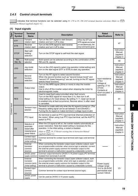
Wiring2.4.5 Control circuit terminalsindicates that terminal functions can be selected using Pr. 178 to Pr. 196 (I/O terminal function selection) (Refer toInstruction Manual (applied) chapter 4.)(1) Input signalsTypeTerminalSymbolTerminalNameDescriptionRatedSpecificationsRefer toContact inputSTFSTRSTOPRH,RM, RLJOGRTMRSRESAUCSSDPCForwardrotation startReverserotation startStart selfholdingselectionMulti-speedselectionJog modeselectionSecondfunctionselectionOutput stopResetTerminal 4 inputselectionPTC inputSelection ofautomaticrestart afterinstantaneouspower failureContact inputcommon (sink)(initial setting)Externaltransistorcommon(source)24VDC powersupply commonExternaltransistorcommon (sink)(initial setting)Contact inputcommon(source)24VDC powersupplyTurn on the STF signal to start forwardrotation and turn it off to stop.Turn on the STR signal to start reverserotation and turn it off to stop.Turn on the STOP signal to self-hold the start signal.When the STF andSTR signals are turnedon simultaneously, thestop command is given.Multi-speed can be selected according to the combination of RH,RM and RL signals.Turn on the JOG signal to select Jog operation (initial setting) andturn on the start signal (STF or STR) to start Jog operation.Turn on the RT signal to select second function.When the second function such as "second torque boost" and"second V/F (base frequency)" are set, turning on the RT signalselects these functions.Turn on the MRS signal (20ms or more) to stop the inverteroutput.Use to shut off the inverter output when stopping the motor byelectromagnetic brake.Used to reset fault output provided when fault occurs.Turn on the RES signal for more than 0.1s, then turn it off.Initial setting is for reset always. By setting Pr.75, reset can be setto enabled only at fault occurrence. Recover about 1s after resetis cancelled.Terminal 4 is made valid only when the AU signal is turned on. (Thefrequency setting signal can be set between 0 and 20mADC.)Turning the AU signal on makes terminal 2 (voltage input) invalid.AU terminal is used as PTC input terminal (thermal protection ofthe motor). When using it as PTC input terminal, set the AU/PTCswitch to PTC.When the CS signal is left on, the inverter restarts automatically atpower restoration. Note that restart setting is necessary for thisoperation. In the initial setting, a restart is disabled.(Refer to Pr. 57 Restart coasting time in Instruction Manual(applied) chapter 4.)Common terminal for contact input terminal (sink logic) and terminalFM.When connecting the transistor output (open collector output), suchas a programmable controller, when source logic is selected, connectthe external power supply common for transistor output to thisterminal to prevent a malfunction caused by undesirable currents.Common output terminal for 24VDC 0.1A power supply (PC terminal).Isolated from terminals 5 and SE.When connecting the transistor output (open collector output), suchas a programmable controller, when sink logic is selected, connectthe external power supply common for transistor output to thisterminal to prevent a malfunction caused by undesirable currents.Common terminal for contact input terminal (source logic).Can be used as 24VDC 0.1A power supply.Input resistance4.7kΩVoltage atopening: 21 to27VDCContacts atshort-circuited: 4to 6mADC47InstructionManual(applied)chapter 449InstructionManual(applied)chapter 4InstructionManual(applied)chapter 4InstructionManual(applied)chapter 49153InstructionManual(applied)chapter 4InstructionManual(applied)chapter 4----------------- —Power supplyvoltage range19.2 to 28.8VDCpermissible loadcurrent 100mA232INSTALLATION AND WIRING19


