

FR-F700 INSTRUCTION MANUAL (BASIC) - MRO Stop
FR-F700 INSTRUCTION MANUAL (BASIC) - MRO Stop
FR-F700 INSTRUCTION MANUAL (BASIC) - MRO Stop
- No tags were found...

You also want an ePaper? Increase the reach of your titles
YUMPU automatically turns print PDFs into web optimized ePapers that Google loves.
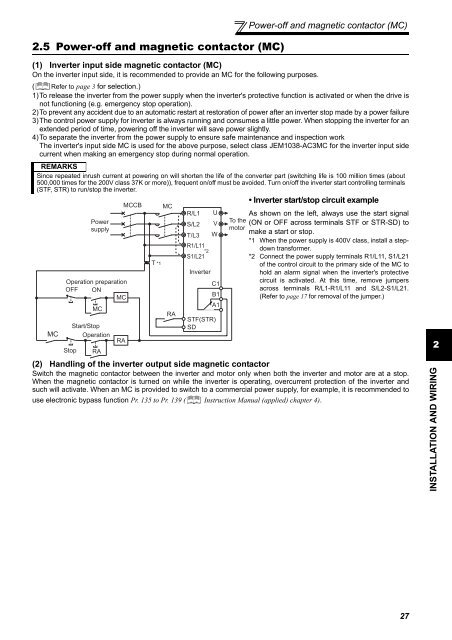
2.5 Power-off and magnetic contactor (MC)Power-off and magnetic contactor (MC)(1) Inverter input side magnetic contactor (MC)On the inverter input side, it is recommended to provide an MC for the following purposes.( Refer to page 3 for selection.)1)To release the inverter from the power supply when the inverter's protective function is activated or when the drive isnot functioning (e.g. emergency stop operation).2)To prevent any accident due to an automatic restart at restoration of power after an inverter stop made by a power failure3)The control power supply for inverter is always running and consumes a little power. When stopping the inverter for anextended period of time, powering off the inverter will save power slightly.4)To separate the inverter from the power supply to ensure safe maintenance and inspection workThe inverter's input side MC is used for the above purpose, select class JEM1038-AC3MC for the inverter input sidecurrent when making an emergency stop during normal operation.REMARKSSince repeated inrush current at powering on will shorten the life of the converter part (switching life is 100 million times (about500,000 times for the 200V class 37K or more)), frequent on/off must be avoided. Turn on/off the inverter start controlling terminals(STF, STR) to run/stop the inverter.MCPowersupplyOperation preparationOFF ONMC<strong>Stop</strong>MCStart/<strong>Stop</strong>OperationRARAMCCBT *1MCRAR/L1 US/L2 VT/L3 WR1/L11*2S1/L21InverterC1B1A1STF(STR)SD• Inverter start/stop circuit exampleAs shown on the left, always use the start signal(ON or OFF across terminals STF or STR-SD) tomake a start or stop.*1 When the power supply is 400V class, install a stepdowntransformer.*2 Connect the power supply terminals R1/L11, S1/L21of the control circuit to the primary side of the MC tohold an alarm signal when the inverter's protectivecircuit is activated. At this time, remove jumpersacross terminals R/L1-R1/L11 and S/L2-S1/L21.(Refer to page 17 for removal of the jumper.)(2) Handling of the inverter output side magnetic contactorSwitch the magnetic contactor between the inverter and motor only when both the inverter and motor are at a stop.When the magnetic contactor is turned on while the inverter is operating, overcurrent protection of the inverter andsuch will activate. When an MC is provided to switch to a commercial power supply, for example, it is recommended touse electronic bypass function Pr. 135 to Pr. 139 ( Instruction Manual (applied) chapter 4).To themotor2INSTALLATION AND WIRING27


