

Electronics-World-1959-05

Create successful ePaper yourself
Turn your PDF publications into a flip-book with our unique Google optimized e-Paper software.
By WILLIAM C. CALDWELL<br />
Rational troubleshooting based on clear -cut rules<br />
can end the futility of hit- and -miss procedures.<br />
GET OUT your meter, put on your<br />
thinking cap, and let's see how we<br />
can put those increasingly popular<br />
transistor portables back into your customers'<br />
pockets almost before they<br />
miss them. It is possible to do this if a<br />
few simple rules and transistor principles<br />
are observed:<br />
Rule 1. Always keep a voltmeter<br />
handy and don't be afraid to use it. A<br />
20,000- ohms -per-volt instrument is perfectly<br />
satisfactory in most cases. In<br />
fact, since it requires no periodic zero<br />
adjustments, it can prevent errors and<br />
save time when reading small voltages<br />
and biases.<br />
Rule 2. Use miniaturized tools for<br />
miniaturized components -small screw-<br />
transistors may also be divided into<br />
three general categories. Low -power<br />
types are generaly used in such stages<br />
as r.f., local oscillator, converter, i.f.,<br />
a.g.c. amplifiers, and small audio amplifiers<br />
(under 50 milliwatts) like those<br />
found in hearing aids. Medium -power<br />
transistors may be used as audio<br />
drivers 150 milliwatts or more) or in<br />
audio -output stages of small portables.<br />
High -power (or simply "power") types<br />
are used in the audio -output stages of<br />
car radios or larger portables that are<br />
capable of one watt of output or more.<br />
Troubleshooting Procedure<br />
Now we are ready to take a typical<br />
portable and apply some of the prin-<br />
ciples involved. The first step always is<br />
to check battery voltage under load<br />
(radio on). This reading should be<br />
within 10 per -cent of rated voltage if<br />
standard zinc -carbon batteries are used<br />
or within 5 per -cent of rated voltage if<br />
mercury batteries are involved. Bad<br />
batteries can cause any number of conditions:<br />
weak, dead, or distorted sound,<br />
or even instability and oscillation.<br />
While at the batteries, it is a very<br />
simple matter to find out how much<br />
current the radio is drawing without<br />
unsoldering any leads if the batteries<br />
are mounted in clips. Simply insert a<br />
piece of paper as an insulator between<br />
one end of a battery and its clip. Switch<br />
the meter to the appropriate milliam-<br />
Save Time on Transistor Radios<br />
drivers, pliers, and a small (20 to 40<br />
watt) soldering iron. Nothing like the<br />
right tool for the job.<br />
Rule 3. Use a system; never just<br />
"hunt or poke" around.<br />
"But what sort of system shall I<br />
use ?" you ask. Simply follow the rules<br />
already mentioned, along with some<br />
other common electronic principles<br />
that will be pointed out here, and<br />
you're in business. Before stating these<br />
principles, let's review some working<br />
facts about transistors:<br />
1. There are two basic transistor<br />
types commonly used in portable<br />
radios, n -p -n and p -n -p. Of these two,<br />
the n -p-n may be more closely compared<br />
to a vacuum tube: one element<br />
emits electrons that are influenced<br />
(biased) by the base as they are attracted<br />
toward a collector that has a<br />
positive potential on it.<br />
2. The p -n -p transistor differs from<br />
the n -p-n primarily in the direction<br />
that electrons flow through it. They<br />
move from collector to emitter, but this<br />
flow is still influenced by the potential<br />
(bias) between base and emitter. With<br />
this reversed internal operation, externally<br />
applied voltages are also<br />
turned around: the most positive potential<br />
is applied to the emitter.<br />
3. In terms of their use in the radio,<br />
112<br />
l<br />
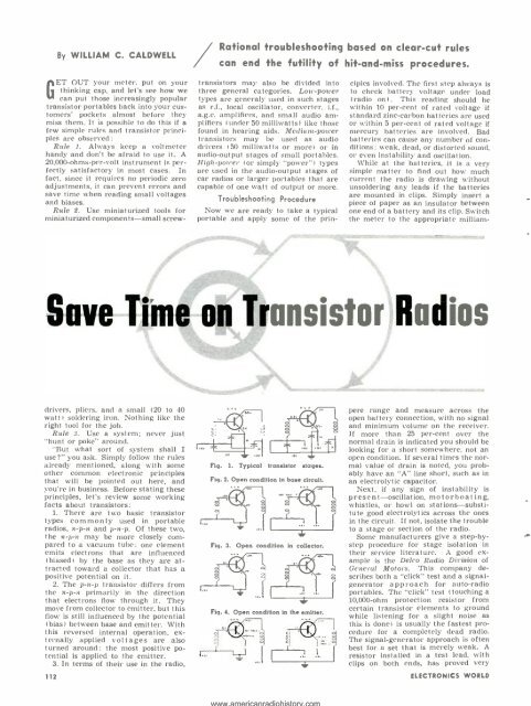
Fig. 1. Typical transistor stages.<br />
Fig. 2. Open condition in base circuit.<br />
Fig. 3. Open condition in collector.<br />
Fig. 4. Open condition in the emitter.<br />
pere range and measure across the<br />
open battery connection, with no signal<br />
and minimum volume on the receiver.<br />
If more than 25 per -cent over the<br />
normal drain is indicated you should be<br />
looking for a short somewhere, not an<br />
open condition. If several times the normal<br />
value of drain is noted, you probably<br />
have an "A" line short, such as in<br />
an electrolytic capacitor.<br />
Next, if any sign of instability is<br />
present -oscillation, motorboating,<br />
whistles, or howl on stations- substitute<br />
good electrolytics across the ones<br />
in the circuit. If not, isolate the trouble<br />
to a stage or section of the radio.<br />
Some manufacturers give a step -by-<br />
step procedure for stage isolation in<br />
their service literature. A good example<br />
is the Delco Radio Division of<br />
General Motors. This company describes<br />
both a "click" test and a signal -<br />
generator approach for auto -radio<br />
portables. The "click" test (touching a<br />
10,000 -ohm protection resistor from<br />
certain transistor elements to ground<br />
while listening for a slight noise as<br />
this is done) is usually the fastest procedure<br />
for a completely dead radio.<br />
The signal -generator approach is often<br />
best for a set that is merely weak. A<br />
resistor installed in a test lead, with<br />
clips on both ends, has proved very<br />
ELECTRONICS WORLD