

Electronics-World-1959-05

You also want an ePaper? Increase the reach of your titles
YUMPU automatically turns print PDFs into web optimized ePapers that Google loves.
2<br />
www.americanradiohistory.com<br />
Q<br />
i<br />
' 2 )<br />
5<br />
o<br />
N<br />
:<br />
ó<br />
)<br />
5<br />
5<br />
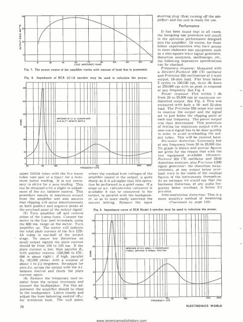
Fig. 7.<br />
A H e5 40 <strong>05</strong> 120 135 i5<br />
_00D IMPEDANCE -OHMS<br />
The power output of the amplifier varies with amount of load that is presented.<br />
Fig. 8. Impedance of RCA LC-IA speake may be used to calculate the power.<br />
100.<br />
00<br />
a0<br />
90<br />
SO<br />
30<br />
1a<br />
\\***,...<br />
IEDANCE MP<br />
OF LC -1A LOUDSPEAKER<br />
IN 10 CU.ET INFINITE BAFFLE<br />
0 n Kn inn<br />
IKC.<br />
IOKC 20KC<br />
FREQUENCY -CPS<br />
upper 12B4A tubes with the five lower<br />
tubes (one pair at a time) for a minimum<br />
meter reading. It is not necessary<br />
to strive for a zero reading. This<br />
can be obtained with a slight re- adjustment<br />
of the d.c. balance control. This<br />
procedure results in maximum output<br />
from the amplifier and also assures<br />
that clipping will occur simultaneously<br />
on both positive and negative peaks at<br />
the overload point of the output signal.<br />
(5) Turn amplifier off and remove<br />
either of the 1 -amp fuses. Connect the<br />
meter to the fuse post terminals, using<br />
the 600 ma. range on the meter. Turn<br />
amplifier on. The meter will indicate<br />
the total plate current of the five 12B-<br />
4A tubes in one -half of the output<br />
stage. To insure low distortion on<br />
small output signals the plate current<br />
should be from 100 to 120 ma. If the<br />
plate current is low, then parallel R2.<br />
with another resistor (220,000 to 470,-<br />
000 is about right) ; if high, parallel<br />
R. (82,000 ohms) with a resistor of<br />
about 1 to 2.2 megohms. Re- adjust for<br />
zero d.c. across the output with the d.c.<br />
balance control and check the plate<br />
current again.<br />
(6) Remove the temporary load resistor<br />
from the output terminals and<br />
connect the loudspeaker. For this adjustment<br />
the amplifier should be close<br />
to the loudspeaker. Listen closely and<br />
adjust the hum balancing control (R.I<br />
for minimum hum. The null point,<br />
72<br />
where the residual hum voltages of the<br />
amplifier cancel in the output, is quite<br />
sharp, so it is advisable that this operation<br />
be performed in a quiet room. If a<br />
scope or a.c. vacuum -tube voltmeter is<br />
available it can be connected to the<br />
output, in parallel with the loudspeaker,<br />
so as to more easily ascertain the<br />
correct setting. Remove the input<br />
N<br />
2<br />
:<br />
o<br />
12<br />
lo<br />
.4<br />
shorting plug (first turning off the amplifier)<br />
and the unit is ready for use.<br />
Performance<br />
It has been found that in all cases,<br />
the foregoing test procedure will result<br />
in the optimum performance designed<br />
into the amplifier. Of course, for those<br />
fellow experimenters who have access<br />
to more elaborate test equipment, such<br />
as a sine -square-wave signal generator,<br />
distortion analyzers, oscilloscope, etc.,<br />
the following impressive specifications<br />
can be checked.<br />
Frequency response: Measured with<br />
a Hewlett -Packard 200 CD oscillator<br />
and Precision 550 oscilloscope at 1 -watt<br />
output, 16 -ohm load. Flat from below<br />
5 cycles to 100,000 cps, three db down<br />
at 250,000 cps with no peak in response<br />
at any frequency. See Fig. 4.<br />
Power response: Flat within 1 db<br />
from 20 to 20,000 cps at maximum undistorted<br />
output. See Fig. 3. This was<br />
measured with both a 16- and 32 -ohm<br />
load. The Precision 550 scope was used<br />
to monitor the output and the signal<br />
set to just below the clipping point at<br />
each test frequency. The power output<br />
was then determined. This procedure<br />
of testing for maximum output with a<br />
sine -wave signal has to be done quickly<br />
in order to avoid overloading the output<br />
tubes. This will be covered later.<br />
Harmonic distortion: Extremely low<br />
at any frequency from 20 to 20,000 cps.<br />
No graph is shown and precise figures<br />
not given for the reason that with the<br />
test equipment available (Hewlett -<br />
Packard 200 CD oscillator and 330B<br />
distortion analyzer, also Precision E300<br />
signal generator) the distortion measurements,<br />
at any output below overload,<br />
were in the realm of the residual<br />
figures of the instruments themselves.<br />
As an estimate we would say that the<br />
harmonic distortion, at any audio frequency<br />
below overload, is below 0.1<br />
per -cent.<br />
Intel-modulation distortion: This is a<br />
more sensitive method of measuring<br />
(Continued on page 110)<br />
Fly. 9. Impedance curve of BLH Model 4 speaker may be used to calculate the power.<br />
9 )<br />
4<br />
)<br />
T<br />
O<br />
0<br />
4PEDANCE OF KLN MODEL < LOUDSPEAKER<br />
1TRERLE SWITCHES IN NORMAL POSITION)<br />
0<br />
f(1 SD IDO IKC.<br />
OKC 2oFC<br />
FREQUENCY- CPS<br />
ELECTRONICS WORLD