

Electronics-World-1959-05

Create successful ePaper yourself
Turn your PDF publications into a flip-book with our unique Google optimized e-Paper software.
' 1<br />
www.americanradiohistory.com<br />
T -41 /ART-I3 TRANSMITTERS<br />
$49.00<br />
100 watt 2.18 MC<br />
cond. with tubes<br />
teal .. nt with r rd,-r ldense.)<br />
LIMITED QUANTITIES -GET YOURS NOW<br />
SCR -214 COMMAND EQUIPMENTS<br />
ALL COMPLETE WITH TUBES<br />
Type Description Used NEW<br />
ItC -453 Receiver 190 -550 l C $14.95 $16.95<br />
ItC -454 Recelter 3 -6 Mc 9.95 12.95<br />
IBC -455 Receiver 6 -9 5Ic 10.95 13.50<br />
BC-450 3- Recelrer Control Box 1.49 1.95<br />
B C-457-TRANSMITTER-4.5.3 Mc. complete<br />
with all rules and crystal. BRAMA NE W... 5.<br />
B C'498 TRANSMITTER-5.3<br />
CC 955<br />
5 ND Mc. Complete<br />
B C -459 TRANSMITTER -T -11.1 Me. c $y10 ,Ú0<br />
Viete 'V Ill) tidies and crystal. 11RAN11 NEW $1D<br />
ARC-5,7-19 TRANSMITTER -3 to 4 Mc. Cont. C, 9 rJ<br />
plot.. with tubes & cry stal. BRAND NFAC.. J<br />
ARC -5/R28 RECEIVERS<br />
u- erhet. DM to ISO Mc In 4 e '1 11nnnel..<br />
e1iComplete with 10 Tubes'<br />
ryS24.45<br />
BRAND NEW<br />
ARC5/T -23 TRANSMITTERS<br />
n cNuEW 2 -832A, 2 -1025 521.50<br />
BRMA<br />
D<br />
ARC -5 MARINE RECEIVERS<br />
Typ, t'010111. Receiver t.' tu R<br />
BRBRAND NEW wate G tolo.<br />
$16.95<br />
SCR 522 2 METER SETS<br />
Terrific annels XtaÌ rcentrrollled. AmpplitudeOO 1dulated<br />
voice. They're gelne fast! EStcellent condition.<br />
SCR -522 TransmitterReceiver, complete with all<br />
111 tubes, top rack and metal case.<br />
COMBINATION Special $29.50<br />
.1<br />
SCR -522 AC -POWER SUPPLY Flt conlstinlr of k u-<br />
and copper oxide meell-<br />
15412 schematic 517.50<br />
REC. MICROWAVE R- III /APR -5<br />
i.e. mlly ntetereil puwer<br />
one 11011, $49.00<br />
AN /ARC -1 Airborne radiophone ,nd to plane Revu<br />
lo. channel sial ntrolled, easily converted<br />
.0 channel, VHF 100 to I ',R Mc AM. Cor<br />
0. w th tulles, mtg rack. dynamotor. $59.50<br />
1R LOW PIttCF.<br />
MOBILE- MARINE<br />
DYNAMOTORS<br />
Input I2V DC. Output: 625<br />
V DC s, 225 Ma., for press -<br />
to -talk intermittent opera.<br />
tion. Shp.. wt. 14 IDs.<br />
DM35 NEW.... $14.95<br />
WINCH ARGER 4156 regulated. Input 13y /13a. Output<br />
.1: 2 II a- Output _ 2' 300y; 223 Regulation<br />
,, ,d to lull load. appr. 5c/o.<br />
$14.9<br />
extremel. ..I,. brand t<br />
W NCNARGER5<strong>05</strong>5.. Input w 12y output 400v/<br />
also used on I<br />
111 96<br />
brand<br />
new<br />
.Ba<br />
SYNCHROSCOPES MODEL TS -34 /AP<br />
t'tui,. - a 2a cathode y tube with a optical megolIt<br />
tj .fr y Le used ulsedr informs-<br />
... microsecond to 'ring.<br />
ation. Mar used for observing sine w<br />
from 30 cycles to 1 megacycle. This nnit la supplied<br />
with carrying case and accessory<br />
cables. Condition Is<br />
ex sellent. All equipment hat checked $95.00<br />
-<br />
GREATEST SURPLUS<br />
BARGAINS. -SCATALOGREE<br />
$5.00 Order Minimum. 25 Deposit on C.O.D: s<br />
Pric. s arc F.O.B. New Haven, Conn.<br />
133 HAMILTON ST.<br />
NEW HAVEN, CONN.<br />
4:4 SALES CO.<br />
positive! Now we come to what ought<br />
to be a dead end, a 300 -µµtd. capacitor<br />
(Crc). The capacitor has the same<br />
voltage at both ends, so I guess he's the<br />
culprit."<br />
"Dead on the ball," approved Tommy,<br />
"and that's the best way to approach<br />
a fault like that too. Put a decent<br />
capacitor in there, one of those<br />
750 -volt types. I'd better give the rest<br />
of the set a check over I guess. Hey!"<br />
he erupted a few minutes later, Who<br />
checked these tubes."<br />
"I did," admitted John, "what's<br />
wrong ?"<br />
"See those shields ?" Tommy pointed<br />
to the i.f. strip. "You must tuck those<br />
little grounding strips inside the shield<br />
(Fig. 3) when you replace it, especially<br />
on this particular model. It has a<br />
tendency to take off into oscillation if<br />
those tubes aren't properly shielded."<br />
The Second G -E Chassis<br />
Jack had been quietly making a voltage<br />
check of the second chassis and<br />
now came up with a list that practically<br />
matched the figures on the schematic.<br />
"That doesn't get us far, does<br />
it ?" he observed disappointedly. "I<br />
guess this one needs a different approach<br />
-and I was looking forward<br />
to playing Sherlock Holmes myself on<br />
this one."<br />
"Don't worry," said Tommy, "there<br />
are other ways of bringing the fault to<br />
justice without tracking him everywhere<br />
he goes. Let's look for some<br />
more evidence." He picked up the low -<br />
capacitance probe and turned up the<br />
intensity control on the scope above<br />
the bench. "Let's have a look for the<br />
sync pips coming through from the<br />
clipper circuit." He attached the probe<br />
to pin 8 of the phase detector in Fig. 1.<br />
"Note we have plenty of spike from<br />
the sync department which disappears<br />
when we tune off- channel. Always a<br />
good idea to remove the signal temporarily<br />
to make sure it is the sync<br />
pulse you are looking at, rather than<br />
some induced signal from the high -<br />
voltage section. And you can see the<br />
saw -tooth there from the horizontal -<br />
discharge tube. Better check along<br />
that line as John did with the other<br />
set. We'd look rather foolish if it was<br />
the same thing and we went batting off<br />
on some other tack." This was done,<br />
but it turned up nothing.<br />
"Now look here," said Tommy, "I<br />
think the best way here would be to<br />
sift the evidence through, exhibit -byexhibit<br />
in the routine. component -<br />
check method. Check each part in the<br />
grid circuit of the reactance tube and<br />
then those between the reactance tube<br />
and the oscillator grid. I'm going to<br />
nip out for an early lunch." When<br />
Tommy returned, the set was working<br />
merrily on the bench, its horizontal<br />
hold as stable as a rock.<br />
"It was this 470 -µpfd. capacitor, C,.,,"<br />
reported Jack. "It has no capacitance<br />
at all according to your checker."<br />
"What does that capacitor do in the<br />
circuit anyway ?" asked John. "I don't<br />
know much about this reactance -tube<br />
business."<br />
"Well," explained Tommy, "you can<br />
regard the reactance tube as being<br />
in parallel with the oscillator tuned<br />
circuit, like this (see Fig. 5). Now the<br />
capacitor that went open was coupling<br />
the reactance tube to the circuit so,<br />
with it open, the reactance tube might<br />
as well not be there for all the good it<br />
does. Under such conditions, when the<br />
oscillator drifts off- frequency, the reactance<br />
tube is not able to change the<br />
phase of the circulating currents in the<br />
oscillator tuning network to compensate<br />
for the drift ... what was that<br />
you said, John ?"<br />
"I just said, 'I pass,' " mumbled<br />
John.<br />
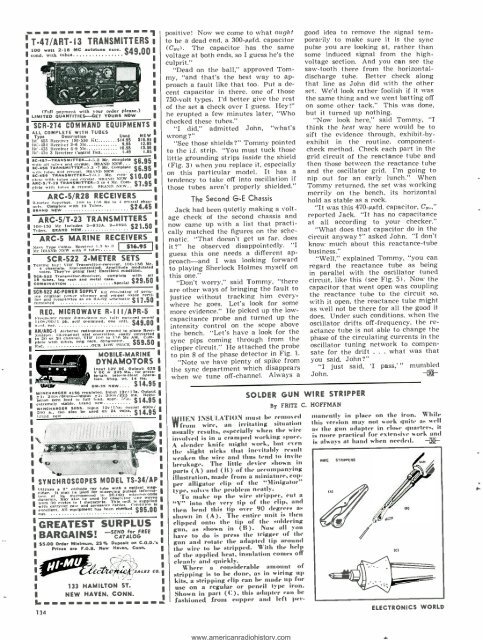
SOLDER GUN WIRE STRIPPER<br />
By FRITZ C. HOFFMAN<br />
WHEN INSULATION must be removed<br />
from wire, an irritating situation<br />
usually results, especially when the wire<br />
involved is in a cramped working space.<br />
A slender knife might work, but even<br />
the slight nicks that inevitably result<br />
weaken the wire and thus tend to invite<br />
breakage. The little device shown in<br />
parts (A) and (B) of the accompanying<br />
illustration, made from a miniature, copper<br />
alligator clip of the "Minigator"<br />
type, solves the problem neatly.<br />
To make up the wire stripper, cut a<br />
"V" into the very tip of the clip, and<br />
then bend this tip over 90 degrees as<br />
shown in (A). The entire unit is then<br />
clipped onto the tip of the soldering<br />
gun, as shown in (B). Now all you<br />
have to do is press the trigger of the<br />
gun and rotate the adapted tip around<br />
the wire to be stripped. With the help<br />
of the applied heat, insulation comes off<br />
cleanly and quickly.<br />
Where a considerable amount of<br />
stripping is to be done, as in wiring up<br />
kits, a stripping clip can be made up for<br />
use on a regular or pencil type iron.<br />
Shown in part (C), this adapter can be<br />
fashioned front copper and left per-<br />
manently in place on the iron. While<br />
this version may not work quite as well<br />
as the gun adapter in close quarters, it<br />
is more practical for extensive work and<br />
is always at band when needed. -30-<br />
ELECTRONICS WORLD