

Electronics-World-1959-05

Create successful ePaper yourself
Turn your PDF publications into a flip-book with our unique Google optimized e-Paper software.
www.americanradiohistory.com<br />
WE HEAR a lot these days about the<br />
value of "talk power" especially<br />
from the gang now using SSB. Although<br />
not directly comparable to SSB,<br />
the modulation system to be described<br />
provides a signal with very high effective<br />
modulation percentage and unusually<br />
high "talk power." It is capable<br />
of excellent voice quality, is easy to<br />
adjust, and a single tube such as the<br />
6L6 will fully modulate up to a kilowatt<br />
peak power input.<br />
The schematic of the modulator, Fig.<br />
lA will he recognized as basically the<br />
circuit of the original clamp modulator<br />
first introduced in 1950 as a simple and<br />
economical step from c.w. to phone operation.<br />
Minor modifications of the<br />
original circuit, as shown in Fig. IB, include<br />
use of an ordinary 6L6 in place<br />
of the 6Y6, elimination of the self -bias<br />
resistor which is not required in this<br />
system, and substitution of the vacuum<br />
tube diodes of a 6SQ7 for the crystal<br />
diode generally used.<br />
Similarities bet ween conventional<br />
clamp tube modulators and this system,<br />
however, end at the modulator.<br />
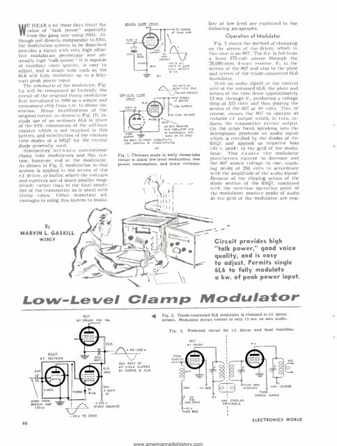
As shown in Fig. 2, modulation in this<br />
system is applied to the screen of the<br />
r.f. driver, or buffer, where the voltages<br />
and currents are of much smaller magnitude,<br />
rather than to the final amplifier<br />
of the transmitter as is usual with<br />
clamp tubes. Other important advantages<br />
in using this system to modu-<br />
A<br />
IeRG_INAL CLAMP CIRCUIT<br />
6Y6<br />
R AS<br />
SIS<br />
LOW -LEVEL CLAMP<br />
CIRCUIT<br />
CURRENT<br />
9F<br />
1HOR<br />
VOLTAGE)<br />
TO SCREEN<br />
OF FINAL A r<br />
POS B NEG<br />
Cr PARTS OF AUDO<br />
c<br />
CYCLE PRESENT<br />
IN DC<br />
la)<br />
Cw<br />
POS PARTS OF<br />
AuD.O CYCLE ONLY<br />
NO NEG PRESENT<br />
TO<br />
OF<br />
SCREEN<br />
BUFFER<br />
LOW CURRENT<br />
B+ (LOW VOLTAGE)<br />
NO BIAS RESISTOR<br />
(BLS MODULATOR AIDS<br />
IN SUPPRESSING POS<br />
CL.. PPE R AUDIO ON ITS GRID.)<br />
(NO BACK -TO -FRONT CONDUCTIVITY,<br />
LESS VARIAT ON IN CHARACTERISTICS)<br />
(GI<br />
Fig. I. Changes made in early clamp -tube<br />
circuit to allow low -level modulation, less<br />
power consumption, and lower voltages.<br />
r<br />
I I I<br />
II<br />
I 1<br />
t!il<br />
late at low level are explained in the<br />
following paragraphs.<br />
Operation of Modulator<br />
Fig. 2 shows the method of clamping<br />
on the screen of the driver, which in<br />
this case is an 807. The d.c. is fed from<br />
a fixed 375 -volt source through the<br />
25,000 -ohm. 4 -watt resistor, R,, to the<br />
screen of the 807 and also to the plate<br />
and screen of the triode -connected 6L6<br />
modulator.<br />
With no audio signal at the control<br />
grid of the unbiased 6L6, the plate and<br />
screen of the tube draw approximately<br />
13 ma. through RI, producing a voltage<br />
drop of 335 volts and thus placing the<br />
screen of the 807 at 40 volts. This, of<br />
course, causes the 807 to operate at<br />
reduced r.f. output which, in turn, reduces<br />
the transmitter carrier output.<br />
On the other hand, speaking into the<br />
microphone produces an audio signal<br />
which is rectified by the diodes of the<br />
6SQ7 and applied as negative bias<br />
(45 v. peak) to the grid of the modulator.<br />
This causes the modulator<br />
plate /screen current to decrease and<br />
the 807 screen voltage to rise, reaching<br />
peaks of 250 volts in accordance<br />
with the amplitude of the audio signal.<br />
Because of the clipping action of the<br />
diode section of the 6SQ7, combined<br />
with the zero -bias operating point of<br />
the modulator, positive peaks of audio<br />
at the grid of the modulator are neg-<br />
By<br />
MARVIN L. GASKILL<br />
W2BCY<br />
Circuit provides high<br />
"talk power," good voice<br />
quality, and is easy<br />
to adjust. Permits single<br />
6L6 to fully modulate<br />
a kw. of peak power input.<br />
Low -Level Clamp Modulator<br />
807<br />
RF DRIVER<br />
FOR PA.<br />
Fig. 2. Triode connected 6L6 modulator is clamped to r.f. driver<br />
screen. Modulator draws current of only 13 ma. on zero audio.<br />
Fig. 3. Preferred circuit for r.f. driver and final amplifier.<br />
.0<strong>05</strong><br />
A F.<br />
6SQ7<br />
RECTIFIER<br />
2015.<br />
r_+ 40-250 V.<br />
6L6<br />
M00.<br />
NEG. PART OF<br />
AF CYCLE CLIPPED<br />
BY DIODES 8 6L6<br />
FROM<br />
EXCITER<br />
R F<br />
RFC<br />
807<br />
DRIVER<br />
ANT<br />
E<br />
60<br />
AUDIO FROM<br />
SPEECH AMP<br />
(45V)<br />
PHONE<br />
CW<br />
-4SV TO ZERO<br />
25K<br />
4 WATT<br />
RI<br />
+3 5V.<br />
(FIXED SOURCE)<br />
TOOK<br />
R2<br />
50K<br />
GRID DRIVE<br />
-45 V<br />
FIXED BIAS<br />
TO MOD<br />
B+<br />
LINK COUPLING<br />
PREFERABLE<br />
t<br />
FIXED BIAS<br />
REOUIRED<br />
FIKE<br />
SCREEN<br />
ROH<br />
SUPPLY<br />
VOLTAGE<br />
ELECTRONICS WORLD