

Electronics-World-1959-05

Create successful ePaper yourself
Turn your PDF publications into a flip-book with our unique Google optimized e-Paper software.
www.americanradiohistory.com<br />
type of phase -splitter, the signal voltage<br />
across the plate and cathode resistors<br />
is essentially of the same magnitude<br />
as the input voltage to the tube.<br />
Normally, this would require a large<br />
voltage from V,. Fortunately, because<br />
the speaker load is also in the input circuit<br />
of the phase -splitter tube and in<br />
the correct sense to provide positive<br />
feedback, a much lower voltage suffices.<br />
In fact, the peak signal voltage to the<br />
input of the phase -splitter need be only<br />
as high as the fixed bias applied to the<br />
power tubes, for maximum output. A<br />
novel feature of this amplifier, as will<br />
be noted in Fig. 1, is that the output<br />
load is part of the input circuits of all<br />
the tubes used in the amplifier for the<br />
purpose of obtaining both positive and<br />
negative feedback. This has been accomplished<br />
without the use of any reactive<br />
components which might produce<br />
undesirable phase shifts.<br />
Amplifier Circuit<br />
The complete amplifier is constructed<br />
on a 13 x 6 x 1% inch chassis.<br />
The schematic is given in Fig. 2<br />
and along with the accompanying<br />
photographs indicates the construction.<br />
A 6AN8 tube is used as a combined<br />
voltage amplifier and phase -splitter.<br />
The unusually large plate load resistor<br />
(1.8 megohms) of the voltage amplifier<br />
produces a gain of over 1000 from this<br />
stage and is entirely practical since the<br />
direct coupling to the phase -splitter<br />
eliminates the usual loading effect of<br />
the following grid resistor.<br />
Each half of the series -connected<br />
push -pull output stage consists of five<br />
type 12B4A tubes connected in parallel.<br />
There are two identical plate current<br />
supplies for this stage, each consisting<br />
simply of a silicon or selenium rectifier<br />
and two 300 pfd. electrolytic capacitors<br />
connected in parallel. The power<br />
transformer is a special low- impedance<br />
unit in which the primary and the 130 -<br />
volt winding feeding the power supplies<br />
for the output stage, each has a<br />
d.c. resistance of less than 1.5 ohms.<br />
This is essential so that the large current<br />
demands of the power tubes, when<br />
peaks of program material are handled,<br />
can be met. Despite the absence of<br />
filter chokes or resistors in these power<br />
supplies, the signal -to-hum ratio of the<br />
amplifier is very high, better than 50<br />
dbm. This is because the amplifier itself<br />
acts as an electronic filter.<br />
To prevent the initial surge of charging<br />
current through the 600 pfd. filter<br />
capacitors (two paralleled 300 Mfd.<br />
a,<br />
r<br />
<<br />
is<br />
Tr<br />
N<br />
70<br />
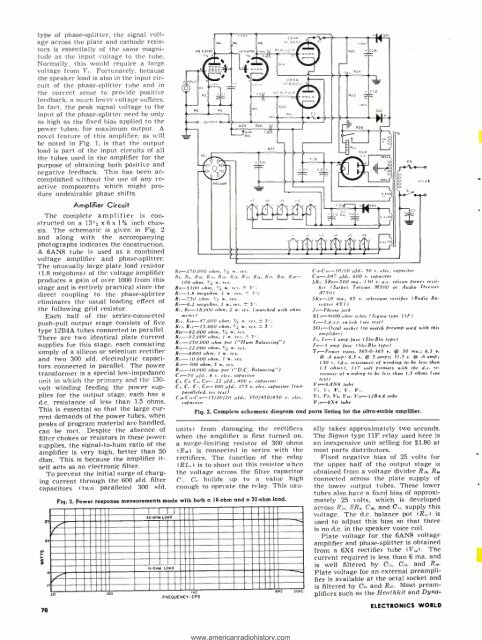
R,- 270.000 ohm. 1/2 w<br />
Rs, Rs, R,e, R,,, R.,. R.,. r Rn. R,.. R,,. R,,.<br />
100 ohm, 1/2 w. res.<br />
R.+ -5100 ohm, 1/2 w. res. ± 5<br />
R, -1.8 megohm. 1 w. res. ± 5';<br />
Rs -750 ohm, 1/2 w. .<br />
Rs -8.2 megohm. 1 w. res. w 5';<br />
R,. Rs- 18,000 ohm, 2 w. res. (matched with ohmmeter)<br />
Rn. Rea- 47.000 ohm, 1/2 w. res. ± 3';<br />
Rn. L,- 15.000 ohm. 1/2 w. res. ± 5';<br />
Ro- 82,000 ohm, 1/2 r<br />
R.3- 82.000 ohm, 1 w. w 5';<br />
L, 230.000 ohm pot ( "Hum Balancing ")<br />
Ro.- 22.000 ohm. 1/2 r. s.<br />
R,,-6800 ohm. 1 w. res re<br />
Rr.- 10.000 ohm, 1 w. res.<br />
Ro-300 ohm, 5 w. res.<br />
Lis-10,000 ohm pot ( "D.C. Balancing ")<br />
C,-50 pfd.. 6 r. elec. topsoitor<br />
C,. Cs. C4. C.-.22 pfd., 400 r. capacitor<br />
Cs, C.. C,. Cs-300 pfd.. 175 r. elec. capacitor (two<br />
paralleled, see text)<br />
C,.- Cu -C- 15/20/20 pfd.. 350/450/450 r. elec.<br />
capacitor<br />
rrtr<br />
V6<br />
° QI"QI' Q1 QI' QI'<br />
tttretttgr<br />
rq<br />
Q<br />
0<br />
1 S<br />
.,r.c<br />
Cu -C-70/10 pfd., 50 r. elec. capacitor<br />
C,s -.047 pfd., 600 r. capacitor<br />
SR,. SL--500 ma., 130 r. a.e. silicon power recti-<br />
fier<br />
(Stokes Taman M500 or Audio Devices<br />
A750)<br />
SRs-20 ma., 65 r. selenium rectifier (Radio Receptor<br />
4Y1)<br />
J ,-Phono jack<br />
RL,-9000 -ohm relay (Sigma type 11F)<br />
S,- S.p.s.t. switch (see text)<br />
SO, -Octal socket (to match preamp used with this<br />
amplifier)<br />
F,. F.-1 amp fuse (Slo -Blo type)<br />
F. ,-3 amp fuse (510-Blo type)<br />
Ts -Power trans. 365.0.365 r. @ 30 ma.; 6.3 r.<br />
(a .6 amp; 6.3 r. @ 3 amps; 31.5 v. @ .6 amp;<br />
130 v. Ida. resistance of winding to be less than<br />
1.5 ohms), 117 volt primary with the d.c. retsistance<br />
of winding to be less than 13 ohms (see<br />
ext)<br />
V, -6AN8 tube<br />
V,. V.. V,, V. V.,<br />
Vs, Vs, Vs, V,,, V,,-1284A tube<br />
V11-6X4 tube<br />
Fig. 2. Complete schematic diagram and parts listing for the ultra -stable amplifier.<br />
units) from damaging the rectifiers<br />
when the amplifier is first turned on,<br />
a surge -limiting resistor of 300 ohms<br />
(R) is connected in series with the<br />
rectifiers. The function of the relay<br />
(RL,) is to short out this resistor when<br />
the voltage across the filter capacitor<br />
C. builds up to a value high<br />
enough to operate the relay. This usu-<br />
Fig. 3. Power response measurements made with both a 16 ohm and a 32 ohm load.<br />
20 100<br />
22-OHM LOAD<br />
*-OHM LOAD<br />
.c io.C. 204C<br />
FREQUENCY -CPS<br />
ally takes approximately two seconds.<br />
The Sigma type 11F relay used here is<br />
an inexpensive unit selling for $1.80 at<br />
most parts distributors.<br />
Fixed negative bias of 25 volts for<br />
the upper half of the output stage is<br />
obtained from a voltage divider R_,, R<br />
connected across the plate supply of<br />
the lower output tubes. These lower<br />
tubes also have a fixed bias of approximately<br />
25 volts, which is developed<br />
across R:.,. SR., C,., and C,., supply this<br />
voltage. The d.c. balance pot (R) is<br />
used to adjust this bias so that there<br />
is no d.c. in the speaker voice coil.<br />
Plate voltage for the 6AN8 voltage<br />
amplifier and phase -splitter is obtained<br />
from a 6X4 rectifier tube (Va). The<br />
current required is less than 6 ma. and<br />
is well filtered by C,,, C,2, and<br />
Plate voltage for an external preamplifier<br />
is available at the octal socket and<br />
is filtered by C. and R., Most preamplifiers<br />
such as the Heathkit and Dyna-<br />
ELECTRONICS WORLD