

Agilent 34980A Multifunction Switch/Measure Unit *34980-90005*
Agilent 34980A Multifunction Switch/Measure Unit *34980-90005*
Agilent 34980A Multifunction Switch/Measure Unit *34980-90005*

You also want an ePaper? Increase the reach of your titles
YUMPU automatically turns print PDFs into web optimized ePapers that Google loves.
3 Features and Functions<br />
Custom A/D Integration Time<br />
Integration time is the period of time the internal DMM’s analog- to- digital<br />
(A/D) converter samples the input signal for a measurement. Integration<br />
time affects the measurement resolution (for better resolution, use a longer<br />
integration time) and measurement speed (for faster measurements, use a<br />
shorter integration time). The default integration time is 1 PLC.<br />
Integration time is specified in number of power line cycles (PLCs).<br />
Select from 0.02, 0.2, 1, 2, 10, 20, 100, or 200 power line cycles.<br />
Only integral number of power line cycles (1, 2, 10, 20, 100, or 200<br />
PLCs) provide normal mode (line frequency noise) rejection.<br />
You can also specify integration time in seconds (this is called aperture<br />
time). Select a value from 300 µs and 1 second, with 4 µs resolution.<br />
The only way to control the reading rate for ac measurements is by<br />
changing the channel delay (see “Channel Delay” on page 120) or by<br />
setting the ac filter to the highest frequency limit (see “AC Low<br />
Frequency Filter” on page 102).<br />
The specified integration time is used for all measurements on the<br />
selected channel. If you have applied Mx+B scaling, have assigned<br />
alarms to the selected channel or are using Monitor mode, those<br />
measurements are also made using the specified integration time.<br />
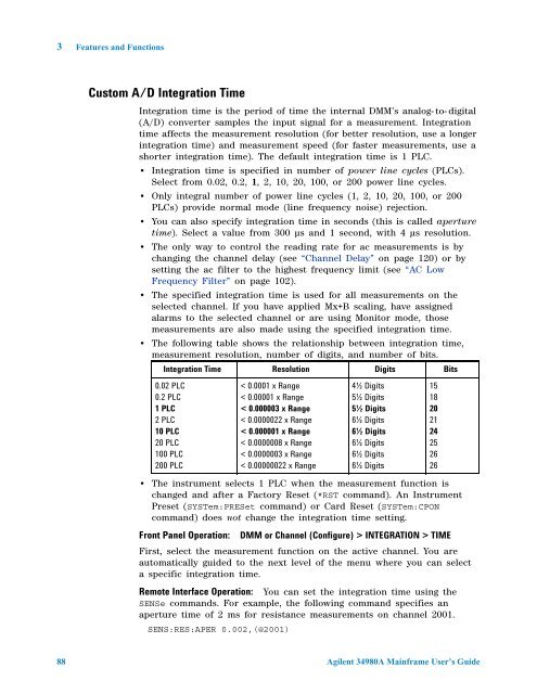
The following table shows the relationship between integration time,<br />
measurement resolution, number of digits, and number of bits.<br />
Integration Time Resolution Digits Bits<br />
0.02 PLC<br />
0.2 PLC<br />
1 PLC<br />
2 PLC<br />
10 PLC<br />
20 PLC<br />
100 PLC<br />
200 PLC<br />
< 0.0001 x Range<br />
< 0.00001 x Range<br />
< 0.000003 x Range<br />
< 0.0000022 x Range<br />
< 0.000001 x Range<br />
< 0.0000008 x Range<br />
< 0.0000003 x Range<br />
< 0.00000022 x Range<br />
The instrument selects 1 PLC when the measurement function is<br />
changed and after a Factory Reset (*RST command). An Instrument<br />
Preset (SYSTem:PRESet command) or Card Reset (SYSTem:CPON<br />
command) does not change the integration time setting.<br />
Front Panel Operation: DMM or Channel (Configure) > INTEGRATION > TIME<br />
First, select the measurement function on the active channel. You are<br />
automatically guided to the next level of the menu where you can select<br />
a specific integration time.<br />
Remote Interface Operation: You can set the integration time using the<br />
SENSe commands. For example, the following command specifies an<br />
aperture time of 2 ms for resistance measurements on channel 2001.<br />
SENS:RES:APER 0.002,(@2001)<br />
4½ Digits<br />
5½ Digits<br />
5½ Digits<br />
6½ Digits<br />
6½ Digits<br />
6½ Digits<br />
6½ Digits<br />
6½ Digits<br />
88 <strong>Agilent</strong> <strong>34980A</strong> Mainframe User’s Guide<br />
15<br />
18<br />
20<br />
21<br />
24<br />
25<br />
26<br />
26


