

1935 Cadillac - GM Heritage Center
1935 Cadillac - GM Heritage Center
1935 Cadillac - GM Heritage Center

Create successful ePaper yourself
Turn your PDF publications into a flip-book with our unique Google optimized e-Paper software.
105<br />
practicable. Burning the carbon, if properly<br />
done, will give good results on these engines at a<br />
much lower cost to the owner.<br />
If this method is used, the carbon should be<br />
allowed to burn slowly to obtain the best possible<br />
results. Quick burning will do only a partial<br />
job. The rate of combustion can be controlled<br />
by the proper regulation of the oxygen supply to<br />
the combustion chamber.<br />
While the carbon is being burned, particular<br />
care must be taken to prevent injury either to<br />
the valves or to the external fittings on the engine.<br />
The proper procedure is as follows:<br />
Remove the spark plug wires and distributor<br />
cover, or use a suitable asbestos cover plate to<br />
protect them during the burning operation.<br />
Remove all spark plugs.<br />
ENGINE<br />
The next step is a matter of extreme importance,<br />
that is, to be sure the valves are both closed in the<br />
cylinder being burned. If the valves are not<br />
closed, they are very likely to be overheated,<br />
causing them to warp.<br />
The only positive way to make sure the valves<br />
are closed is to use a test light and crank the engine<br />
to the firing point on that cylinder. See Fig. 20,<br />
Plate 38.<br />
Allow the carbon to burn slowly until it has all<br />
been burned.<br />
Burn out all of the left-hand cylinders first, in<br />
the order in which they fire; then burn the right<br />
hand cylinders. The firing order, is, of course,<br />
indicated on the distributor cap.<br />
Removal of carbon in the V-8 engines should<br />
be done by scraping as in the past.<br />
14. Main Bearing Clearance<br />
Use dial indicator and special fixture (Tool No<br />
HM-65530) for checking bearing clearances. If<br />
bearings are found to be worn beyond specified<br />
limits they should be replaced. Replacement<br />
bearings are furnished to exact size and do not<br />
require reaming or scraping. No shims or liners<br />
are used on the main bearings and no attempt<br />
should be made to take up if worn.<br />
Always install new wooden plugs in grooves in<br />
sides of rear main bearing cap in <strong>Cadillac</strong> engine<br />
to prevent oil leaks around the cap. These plugs<br />
should be well greased to facilitate installation in<br />
the grooves.-<br />
15. Cleaning Oil Filter on 370-D and 452-D<br />
A Cuno disc-type self-cleaning oil filter is used<br />
on the 370-D and 452-D cars.<br />
The oil, in circulating through the filter, passes<br />
between thin rotating discs, stacked one upon<br />
another, and separated a few thousandths of an<br />
inch by a series of thin stationary plates. The<br />
filtering discs are mounted on a shaft which<br />
extends above the filter and is connected to the<br />
brake linkage in such a way that the discs are<br />
rotated a partial turn each time the brakes are<br />
applied. -<br />
When the filtering discs are rotated the accumulated<br />
sediment is scraped off by the stationary<br />
plates and falls to the bottom of the tank.<br />
The only attention required is the draining of<br />
the tank every 6000 miles.<br />
16. Using Stud for Removing V-8 Cylinder<br />
Heads<br />
The cylinder blocks used on <strong>Cadillac</strong> V-8 cars<br />
are not equipped with studs for attaching the<br />
cylinder heads. Instead, cap screws are used<br />
because of the necessity of turning the head<br />
slightly counter-clockwise, when removing, to<br />
clear the hood shelf.<br />
When removing or installing cylinder heads,<br />
particular care must be taken to hold the head in<br />
position. If this precaution is not taken, there is<br />
a possibility of the head striking and bending<br />
those valves which are open.<br />
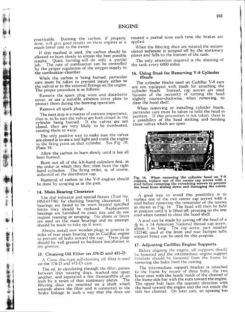
Fig. 16. When removing the cylinder head on V-8<br />
engines, replace one of the center cap screws with a<br />
stud before removing the remaining screws to prevent<br />
the head from sliding down and damaging the valves.<br />
A good way to avoid this possibility is to<br />
replace one of the two center cap screws with a<br />
stud before removing the remainder of the screws<br />
as shown in Fig. 16. The head will then be held<br />
in position until it is lifted off, pivoting on the one<br />
stud when turned to clear the hood shelf.<br />
A stud can be made by sawing off the head of a<br />
-r\ in. x 14 American National thread cap screw,<br />
about 3 in. long. The cap screw, part number<br />
122340, used at the front and rear bumper tube<br />
support brace can be used for this purpose.<br />
17. Adjusting <strong>Cadillac</strong> Engine Supports<br />
Before aligning the engine, all supports should<br />
be loosened and the intermediate engine support<br />
brackets should be loosened from the frame by<br />
removing the bolts from the casting.<br />
The intermediate support bracket is attached<br />
to the frame by means of three bolts, the two<br />
lower ones with the heads inside of the channel of<br />
the frame side bar with the nuts toward the engine.<br />
The upper bolt faces the opposite direction with<br />
the head toward the engine and the nut inside the<br />
side bar channel. On later cars, an opening has


