

1935 Cadillac - GM Heritage Center
1935 Cadillac - GM Heritage Center
1935 Cadillac - GM Heritage Center

You also want an ePaper? Increase the reach of your titles
YUMPU automatically turns print PDFs into web optimized ePapers that Google loves.
129<br />
GASOLINE SYSTEM<br />
during the warming-up period. As the engine<br />
becomes warm, the tension of the thermostat<br />
gradually lessens and the inrushing air becomes<br />
the dominant force, thus moving the choke valve<br />
to the wide open position for normal operating<br />
temperatures.<br />
INTAKE<br />
SILENCER<br />
An intake silencer is used on all models. The<br />
silencer silences the intake noises at all engine<br />
speeds under various throttle openings. There are<br />
no moving parts or baffle plates on these silencers.<br />
A feature of the air silencer is the copper gauge<br />
air cleaner which is designed to catch any dust or<br />
lint in the air before it is drawn into the carburetor.<br />
It is automatic in operation and requires no attention<br />
other than periodic cleaning and oiling.<br />
The intake silencers on the <strong>Cadillac</strong> cars are<br />
connected to the radiator in such a way as to<br />
secure fresh, cool air through a passage between<br />
the radiator core and casing instead of using the<br />
warm air from under the hood. This arrangement<br />
permits the use of higher compression and greater<br />
spark advance and results in increased power and<br />
engine performance.<br />
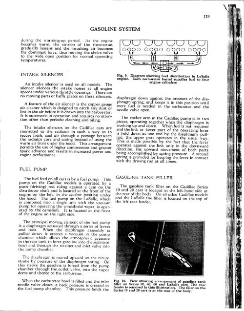
Fig. 9. Diagram showing fuel distribution in LaSalle<br />
engine. Each carburetor barrel supplies fuel to four<br />
engine cylinders<br />
diaphragm down against the pressure of the diaphragm<br />
spring, and keeps it in this position until<br />
more fuel is needed in the carburetor and the<br />
needle valve open.<br />
The rocker arm in the <strong>Cadillac</strong> pump is in two<br />
pieces, operating together when the diaphragm is<br />
working up and down. When fuel is not required<br />
and the link or lower part of the operating lever<br />
is held down at one end by the diaphragm pullrod,<br />
the upper part operates in the usual way.<br />
This is made possible by the fact that the lever<br />
operates against the link only in the downward<br />
direction, the upward movement of both parts<br />
being accomplished by spring pressure. A second<br />
spring is provided for keeping the lever in contact<br />
with the driving rod at all times.<br />
FUEL<br />
PUMP<br />
The fuel feed on all cars is by a fuel pump. This<br />
pump on the <strong>Cadillac</strong> models is operated by a<br />
push (driving) rod riding against a cam on the<br />
distributor shaft and is located at the front of the<br />
engine on the left, in the coolest position under<br />
the hood. The fuel pump on the LaSalle, which<br />
is combined into a single unit with the vacuum<br />
pump for operating the windshield wiper, is operated<br />
by the camshaft. It is located at the front<br />
of the engine on the right side.<br />
GASOLINE TANK FILLER<br />
The gasoline tank filler on the <strong>Cadillac</strong> Series<br />
10 and 20 cars is located in the left-hand side at<br />
the rear of the body. On all other <strong>Cadillac</strong> models<br />
and the LaSalle the filler is located on the top of<br />
the left rear fender.<br />
The principal moving element of the fuel pump<br />
is a diaphragm actuated through a series of levers<br />
and rods. When the diaphragm assembly is<br />
pulled down, it creates a vacuum in the pump<br />
chamber which allows the atmospheric pressure<br />
in the rear tank to force gasoline into the sediment<br />
bowl and through the strainer and inlet valve into<br />
the pump chamber.<br />
The diaphragm is moved upward on the return<br />
stroke by pressure of the diaphragm spring. On<br />
this stroke the gasoline is forced from the pump<br />
chamber through the outlet valve, into the vapor<br />
dome and thence to the carburetor.<br />
When the carburetor bowl is filled and the inlet<br />
needle valve closes, a back pressure is created in<br />
the fuel pump chamber. This pressure holds the<br />
Fig. 10. View showing arrangement of gasoline tank<br />
filler on Series 30, 40, 60 and LaSalle cars. The rear<br />
fender is removed in this illustration. The filler on the<br />
Series 10 and 20 cars is at the rear of the body.


