

1935 Cadillac - GM Heritage Center
1935 Cadillac - GM Heritage Center
1935 Cadillac - GM Heritage Center

Create successful ePaper yourself
Turn your PDF publications into a flip-book with our unique Google optimized e-Paper software.
<strong>Cadillac</strong> Preliminary Service Information 25<br />
Rela<br />
Solenoid Windings<br />
Ammeter<br />
flLlenl<br />
Plunge,<br />
engine starts running, the solenoid circuit is automatically<br />
opened which allows the starting gear to<br />
disengage from the flywheel. The relay circuit is<br />
controlled by the ignition switch in such a manner<br />
that the solenoid is inoperative unless the ignition<br />
switch is in the "on" position.<br />
I<br />
\—'<br />
Starter Button \ Storage ^ r<br />
(Generator Ignition'Switch<br />
I. Battery<br />
' Starting Motor<br />
Fig. 32. Diagram of the starting motor<br />
circuit<br />
the "C" series cars. The control for the starting<br />
motor, however, is entirely new and cor/sists of a<br />
solenoid mounted on top of the starting' motor, a<br />
relay and a starter button on the instrument panel.<br />
To start the engine in the new cars, it is only<br />
necessary for the driver to turn on the ignition<br />
switch and then press in on the hand starter button.<br />
The solenoid operates the starter engaging<br />
mechanism and is controlled by a relay'both of<br />
which are shown in Fig. 30. The relay in turn is<br />
controlled by the starter push button on the instrument<br />
panel and serves the same purpose in the<br />
solenoid and starter button circuit as docs the horn<br />
relay in tb.6 horn circuit; that is, instead of a heavy<br />
wire being used between the starter button and the<br />
solenoid, heavy wires are used only between the<br />
relay and the solenoid. A smaller wire is used between<br />
the relay and the starter button. This will<br />
eliminate the passing of a heavy current through<br />
the starter button and making a voltage drop in<br />
the wiring.<br />
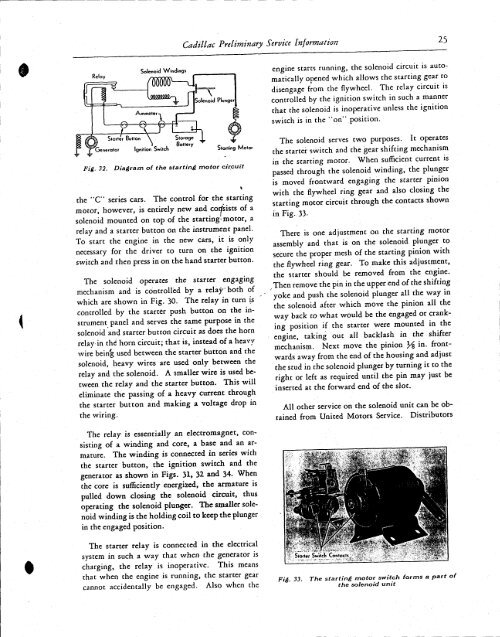
The solenoid serves two purposes. It operates<br />
the starter switch and the gear shifting mechanism<br />
in the starting motor. When sufficient current is<br />
passed through the solenoid winding, the plunger<br />
is moved frontward engaging the starter pinion<br />
with the flywheel ring gear and also closing the<br />
starting motor circuit through the contacts shown<br />
in Fig. 33-<br />
There is one adjustment on the starting motor<br />
assembly and that is on the solenoid plunger to<br />
secure the proper mesh of the starting pinion with<br />
the flywheel ring gear. To make this adjustment,<br />
the starter should be removed from the engine.<br />
. Then remove the pin in the upper end of the shifting<br />
yoke and push the solenoid plunger all the way in<br />
the solenoid after which move the pinion all the<br />
way back to what would be the engaged or cranking<br />
position if the starter were mounted in the<br />
engine, taking out all backlash in the shifter<br />
mechanism. Next move the pinion }/% in. frontwards<br />
away from the end of the housing and adjust<br />
the stud in the solenoid plunger by turning it to the<br />
right or left as required until the pin may just be<br />
inserted at the forward end of the slot.<br />
All other service on the solenoid unit can be obtained<br />
from United Motors Service. Distributors<br />
The relay is essentially an electromagnet, consisting<br />
of a winding and core, a base and an armature.<br />
The winding is connected in series with<br />
the starter button, the ignition switch and the<br />
generator as shown in Figs. 31, 32 and 34. When<br />
the core is sufficiently energized, the armature is<br />
pulled down closing the solenoid circuit, thus<br />
operating the solenoid plunger. The smaller solenoid<br />
winding is the holding coil to keep the plunger<br />
in the engaged position.<br />
The starter relay is connected in the electrical<br />
system in such a way that when the generator is<br />
charging, the relay is inoperative. This means<br />
that when the engine is running, the starter gear<br />
cannot accidentally be engaged. Also when the<br />
Fig. 33. The starting motor switch forms a part of<br />
the solenoid unit


