

1935 Cadillac - GM Heritage Center
1935 Cadillac - GM Heritage Center
1935 Cadillac - GM Heritage Center

You also want an ePaper? Increase the reach of your titles
YUMPU automatically turns print PDFs into web optimized ePapers that Google loves.
<strong>Cadillac</strong> Preliminary Service Information<br />
5<br />
this new type of steering system, despite the use<br />
of vGj||ijre&>cting fiont springs, the accuracy of<br />
ste?H«gSne car, especially at high speeds is greater<br />
than c*ri- possibly be obtained with the conventional<br />
type of front axle.<br />
The new front wheel suspension system should<br />
be thoroughly studied in order that the principles<br />
of construction and operation may be well understood.<br />
This is necessary for intelligent and<br />
efficient servicing of this new assembly.<br />
Adjustments<br />
Maintenance of correct front wheel alignment<br />
is of special importance to service. f<br />
The amount of caster in the new cars is 1 to 2°<br />
with the weight of the car on the front wheels.<br />
The caster may be checked in the same manner as<br />
on previous model cars or with Tool No. J-631<br />
using it against the pads on the front side of the<br />
steering knuckle supports. See Fig. 2. No method<br />
should be used, however, that will necessitate<br />
raising the wheels off the floor.<br />
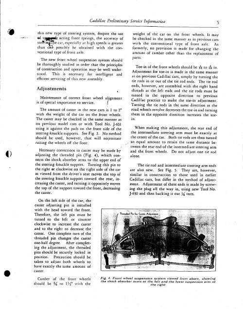
Necessary corrections in caster may be made by<br />
adjusting the threaded pin (Fig. 4), which connects<br />
the shock, absorber arms to the upper end of<br />
the steering-knuckle support. Turning this pin to<br />
the right ar clockwise on the right side of the car<br />
as viewed from the driver's seat moves the top of<br />
the steering knuckle support toward the rear, increasing<br />
the caster, and turning it oppositely moves<br />
the top of the support toward the front, decreasing<br />
the caster.<br />
weight of the car on the front wheels. It may<br />
be checked in the same manner as in previous cars<br />
with the conventional type of front axle. As<br />
formerly, no provision is made for changing the<br />
amount of camber ocher than the replacement of<br />
parts.<br />
Toe-in of the front wheels should be IT to rs in.<br />
Adjustment for toe-in is made in the same manner<br />
as on previous <strong>Cadillac</strong> cars, simply by turning the<br />
tie rods in or out of the tie rod ends. The tie rod<br />
ends, however, are assembled with the right hand<br />
threads at the left ends and the tie rods must be<br />
turned in the opposite direction to previous<br />
<strong>Cadillac</strong> practice to make the toe-in adjustment.<br />
Turning the tie rods in the same direction as the<br />
road wheels revolve decreases the toe-in and turning<br />
them in the opposite direction increases the toein.<br />
When making this adjustment, the rear end of<br />
the intermediate steering arm must be exactly at<br />
the center of the car. Both tie rods are then turned<br />
. an equal amount to retain the same distance between<br />
the rear end of the intermediate steering arm<br />
and the front wheels. Do not adjust one tie rod<br />
alone.<br />
The tie rod and intermediate steering arm ends<br />
are also new. See Fig. 5- They are, however,<br />
similar in construction to those used in earlier<br />
<strong>Cadillac</strong> cars, but differ in the method of adjustment.<br />
Adjustment of these ends is made by screwing<br />
the plug all the way in, using new Tool No.<br />
J-630 and then backing it out }4 turn.<br />
On the left side of the car, the<br />
caster adjusting pin is installed<br />
with the head toward the front.<br />
Therefore, the left pin must be<br />
turned to the left or counter<br />
clockwise to increase the caster<br />
and to the right to decrease the<br />
caster. One complete turn of the<br />
threaded pin changes the caster<br />
one-half degree. After completing<br />
the adjustment, the threaded<br />
pins should be securely locked in<br />
position. Precaution should be<br />
taken to adjust both wheels to<br />
have exactly the same amount of<br />
caster.<br />
Camber of the front wheels<br />
should be % to 1½° with the<br />
Threaded Pin for Casrei Adiuslmenl<br />
Fig. 4. Front wheel suspension system viewed from above, showing<br />
the shock absorber arms at the left and the lower suspension arm at<br />
the right


