position / speed mode - Harmonic Drive LLC
position / speed mode - Harmonic Drive LLC
position / speed mode - Harmonic Drive LLC

You also want an ePaper? Increase the reach of your titles
YUMPU automatically turns print PDFs into web optimized ePapers that Google loves.
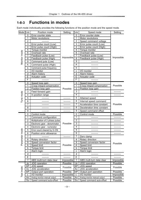
1-8-3 Functions in <strong>mode</strong>s<br />
Chapter 1Outlines of the HA-655 driver<br />
Each <strong>mode</strong> individually provides the following functions of the <strong>position</strong> <strong>mode</strong> and the <strong>speed</strong> <strong>mode</strong>.<br />
Mode Code Position <strong>mode</strong> Setting Code Speed <strong>mode</strong> Setting<br />
0 Error counter state 0 Error counter state<br />
1 Motor revolutions 1 Motor revolutions<br />
2 2 Speed command voltage<br />
3 Error pulse count (Low) 3 Error pulse count (Low)<br />
4 Error pulse count (High) 4 Error pulse count (High)<br />
5 Torque monitor 5 Torque monitor<br />
6 Overload rate 6 Overload rate<br />
7 Feedback pulse (Low) 7 Feedback pulse (Low)<br />
8 Feedback pulse (High)<br />
Impossible<br />
8 Feedback pulse (High)<br />
Impossible<br />
9 Command pule (Low) 9 <br />
A Command pulse (High) A <br />
b Command pulse frequency b <br />
c I/O monitor c I/O monitor<br />
d Alarm history d Alarm history<br />
E Actuator code E Actuator code<br />
F<br />
<br />
F<br />
<br />
Monitor <strong>mode</strong><br />
Tune <strong>mode</strong><br />
Parameter <strong>mode</strong><br />
Test <strong>mode</strong><br />
0 Speed loop gain 0 Speed loop gain<br />
1 S-loop integral compensation 1 S-loop integral compensation Possible<br />
2 Position loop gain Possible 2 Position loop gain<br />
3 Feed-forward gain 3 <br />
4 In-<strong>position</strong> range<br />
4 <br />
5 5 Attained <strong>speed</strong><br />
6 6 Internal <strong>speed</strong> command<br />
7 7 Acceleration time constant Possible<br />
8 8 Deceleration time constant<br />
9 9 Speed command offset<br />
0 Control <strong>mode</strong> 0 Control <strong>mode</strong> Possible<br />
1 Command configuration 1 <br />
2 Multiplication of 2-phase pulse 2 <br />
3 Electronic gear - denominator Possible 3 <br />
4 Electronic gear - numerator 4 <br />
5 Error count cleared by S-ON 5 <br />
6 Position error allowance<br />
6 <br />
7 7 Zero clamp<br />
8 Rotary direction 8 Rotary direction<br />
9 Speed conversion factor 9 Speed conversion factor<br />
A Speed limit Possible A Speed limit<br />
Possible<br />
b Torque limit b Torque limit<br />
c Alarm logic<br />
c Alarm logic<br />
d d <br />
E E <br />
f ABS multi-turn data clear Impossible f ABS multi-turn data clear Impossible<br />
Jo JOG operation Possible Jo JOG operation Possible<br />
SP JOG <strong>speed</strong><br />
SP JOG <strong>speed</strong><br />
Possible<br />
Ac JOG acceleration<br />
Ac JOG acceleration<br />
Possible<br />
InP Output port operation Possible InP Output port operation Possible<br />
c I/O monitor Impossible c I/O monitor Impossible<br />
An Analog monitor manual output Possible An Analog monitor manual output Possible<br />
So Speed command auto-offset Possible So Speed command auto-offset Possible<br />
- 9 -