position / speed mode - Harmonic Drive LLC
position / speed mode - Harmonic Drive LLC
position / speed mode - Harmonic Drive LLC

You also want an ePaper? Increase the reach of your titles
YUMPU automatically turns print PDFs into web optimized ePapers that Google loves.
Chapter 5 Operations<br />
5-1-2Setting parameters<br />
Following test run of the actuator you can set the parameters via the parameter <strong>mode</strong>.<br />
All parameters are dependant upon the driven machine system. The abstracts of the parameters in the<br />
parameter <strong>mode</strong> are described in the table below:<br />
Name Description Parameters<br />
0: Control <strong>mode</strong> Selecting [<strong>position</strong> <strong>mode</strong>] or [<strong>speed</strong> <strong>mode</strong>]<br />
[Position <strong>mode</strong>]pulse train signal<br />
[Speed <strong>mode</strong>]analog voltage signal<br />
0: <strong>position</strong> <strong>mode</strong><br />
1: <strong>speed</strong> <strong>mode</strong><br />
1: Command<br />
configuration<br />
2: Multiplication of<br />
2-phase pulse<br />
3: Electric gear -<br />
denominator<br />
Selecting a command configuration from<br />
[2-pulse type],[1-pulse type]and [2-phase pulse type]<br />
Command pulse train multiplication when command<br />
configuration is [2-phase pulse type].<br />
Denominator of electronic gear function to make simple<br />
relation between displacement of driven mechanism and<br />
command pulses.<br />
0: 2-pulse type<br />
1: 1-pulse type<br />
2: 2 phase pulse type<br />
1: Same count of command<br />
2: Double of command<br />
4: Four times of command<br />
Integer from 1 to 50<br />
4: Electric gear - Numerator of the electronic gear function Integer from 1 to 50<br />
numerator<br />
5: Error count clear<br />
by Servo-ON<br />
Clearing error count or not clearing by [servo-ON] input<br />
signal.<br />
0: No function<br />
1: Clears it<br />
6: Allowable Allowance of <strong>position</strong> error count Alarm 60 1 to 1000<br />
<strong>position</strong> error<br />
7: Zero clamp Clamp <strong>position</strong> or not in [<strong>speed</strong> <strong>mode</strong>] 0: No function<br />
1: Zero clamp<br />
8: Rotary direction Specifying the relation between command polarity and<br />
rotary direction<br />
0: FWD for positive com.<br />
1:REV for positive com.<br />
9: Speed<br />
Rotary <strong>speed</strong> to command of 10V in [<strong>speed</strong> <strong>mode</strong>] 1 to max. motor <strong>speed</strong><br />
conversion factor<br />
A: Speed limit Upper limit of motor <strong>speed</strong> 1 to max. motor <strong>speed</strong><br />
b: Torque limit Upper limit of motor torque; 100% to max. torque 1 to 100<br />
c: Alarm logic Output signal logic of the alarm 0: normal close<br />
1: normal open<br />
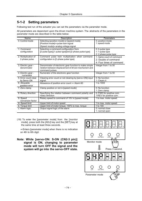
(19) To enter the [parameter <strong>mode</strong>] from the [monitor<br />
<strong>mode</strong>], press both the [ADJ] key and the [SET] key at<br />
the same time at least three seconds.<br />
Enters [parameter <strong>mode</strong>] when there is no indication<br />
on 4th to 6th digit.<br />
Note: While [servo-ON: S-ON (CN2-3 pin)]<br />
signal is ON, changing to parameter<br />
<strong>mode</strong> will turn OFF the signal and the<br />
system will go into the servo-OFF state.<br />
U P D O W N A D J S E T<br />
Monitor <strong>mode</strong><br />
Press 3 second.<br />
U P<br />
D O W N<br />
S E T<br />
Parameter <strong>mode</strong><br />
- 74 -