position / speed mode - Harmonic Drive LLC
position / speed mode - Harmonic Drive LLC
position / speed mode - Harmonic Drive LLC

Create successful ePaper yourself
Turn your PDF publications into a flip-book with our unique Google optimized e-Paper software.
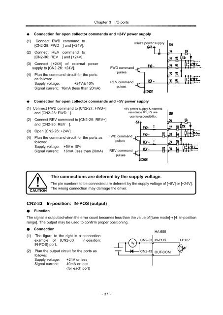
Chapter 3I/O ports<br />
Connection for open collector commands and +24V power supply<br />
(1) Connect FWD command to<br />
[CN2-28: FWD] and [+24V].<br />
User’s power supply<br />
(2) Connect REV command to<br />
[CN2-30: REV] and [+24V].<br />
(3) Connect [+24V] of external power<br />
supply to [CN2-26: +24V].<br />
(4) Plan the command circuit for the ports<br />
as follows:<br />
Supply voltage: +24V10%<br />
Signal current: 16mA (less than 20mA)<br />
FWD command<br />
pulses<br />
REV command<br />
pulses<br />
Connection for open collector commands and +5V power supply<br />
(1) Connect FWD command to [CN2-27: FWD+]<br />
and [CN2-28: FWD].<br />
(2) Connect REV command to [CN2-29: REV+]<br />
and [CN2-30: REV].<br />
(3) Open [CN2-26: +24V].<br />
(4) Plan the command circuit for the ports as<br />
follows:<br />
Supply voltage: +5V10%<br />
Signal current: 16mA (less than 20mA)<br />
FWD command<br />
pulses<br />
REV command<br />
pulses<br />
+5V power supply & external<br />
resistance R1, R2 are<br />
user’s responsibility.<br />
CAUTION<br />
The connections are deferent by the supply voltage.<br />
The pin numbers to be connected are deferent by the supply voltage of [+5V] or [+24V].<br />
The wrong connection may damage the driver.<br />
CN2-33In-<strong>position</strong>: IN-POS (output)<br />
Function<br />
The signal is outputted when the error count becomes less than the value of [tune <strong>mode</strong>][4: -<strong>position</strong> in<br />
range]. The output may be used to confirm proper <strong>position</strong>ing.<br />
Connection<br />
(1)The figure to the right is a connection<br />
example of [CN2-33 in-<strong>position</strong>:<br />
IN-POS] port.<br />
Ry<br />
CN2-33<br />
HA-655<br />
IN-POS<br />
TLP127<br />
(2)Plan the output circuit for the ports as<br />
follows:<br />
Supply voltage: +24V or less<br />
Signal current: 40mA or less<br />
(for each port)<br />
CN2-43<br />
OUT-COM<br />
- 37 -