position / speed mode - Harmonic Drive LLC
position / speed mode - Harmonic Drive LLC
position / speed mode - Harmonic Drive LLC

Create successful ePaper yourself
Turn your PDF publications into a flip-book with our unique Google optimized e-Paper software.
Chapter 2Functions<br />
Note 1: Both output signals of phase-A and phase-B are settled at LOW-level. To settle at LOW-level, at<br />
least three pulses are outputted. Make a sequence for the host device ignoring outputted pulses while the<br />
phase-Z is LOW-level before generating an absolute pulse train, and during other LOW-level duration of<br />
the phase-Z signal.<br />
Note 2: An absolute pulse train for single-turn encoder is outputted after around 1 ms of outputting<br />
phase-Z signal.<br />
Note 3: The servo-ON signal is unaccepted until completing the transmission of a set of absolute pulse<br />
trains by the [absolute data request] signal.<br />
Note 4: The [alarm 57] occurs if the single-turn encoder rotates more than 127 resolvable <strong>position</strong> while<br />
the multi-turn counter is transmitting an absolute pulse train.<br />
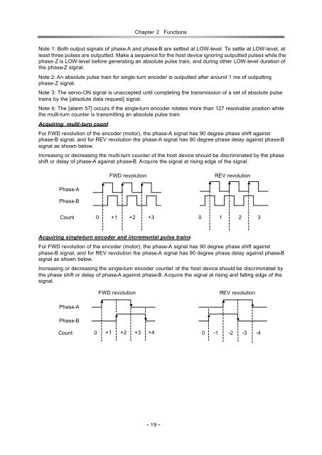
Acquiring multi-turn count<br />
For FWD revolution of the encoder (motor), the phase-A signal has 90 degree phase shift against<br />
phase-B signal, and for REV revolution the phase-A signal has 90 degree phase delay against phase-B<br />
signal as shown below.<br />
Increasing or decreasing the multi-turn counter of the host device should be discriminated by the phase<br />
shift or delay of phase-A against phase-B. Acquire the signal at rising edge of the signal.<br />
FWD revolution<br />
REV revolution<br />
Phase-A<br />
Phase-B<br />
Count<br />
0 +1 +2 +3 0 123<br />
Acquiring single-turn encoder and incremental pulse trains<br />
For FWD revolution of the encoder (motor), the phase-A signal has 90 degree phase shift against<br />
phase-B signal, and for REV revolution the phase-A signal has 90 degree phase delay against phase-B<br />
signal as shown below.<br />
Increasing or decreasing the single-turn encoder counter of the host device should be discriminated by<br />
the phase shift or delay of phase-A against phase-B. Acquire the signal at rising and falling edge of the<br />
signal.<br />
FWD revolution<br />
REV revolution<br />
Phase-A<br />
Phase-B<br />
Count 0 +1<br />
z<br />
+2<br />
z<br />
+3<br />
z<br />
+4<br />
z<br />
0 -1 -2 -3 -4<br />
- 19 -