position / speed mode - Harmonic Drive LLC
position / speed mode - Harmonic Drive LLC
position / speed mode - Harmonic Drive LLC

You also want an ePaper? Increase the reach of your titles
YUMPU automatically turns print PDFs into web optimized ePapers that Google loves.
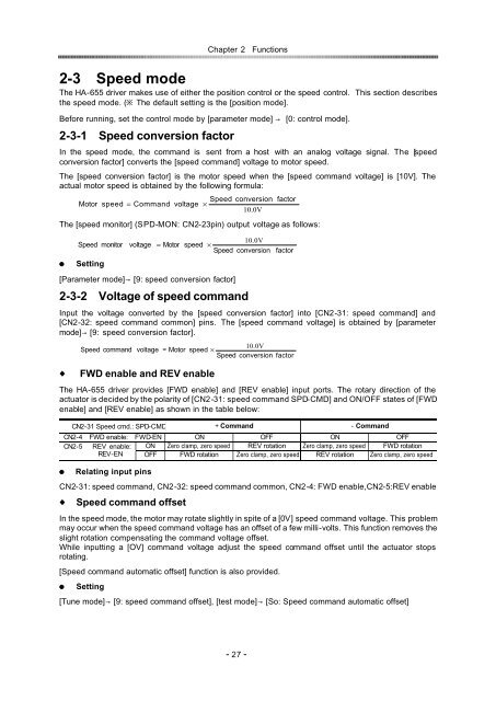
2-3Speed <strong>mode</strong><br />
Chapter 2Functions<br />
The HA-655 driver makes use of either the <strong>position</strong> control or the <strong>speed</strong> control. This section describes<br />
the <strong>speed</strong> <strong>mode</strong>. ( The default setting is the [<strong>position</strong> <strong>mode</strong>].<br />
Before running, set the control <strong>mode</strong> by [parameter <strong>mode</strong>] [0: control <strong>mode</strong>].<br />
2-3-1Speed conversion factor<br />
In the <strong>speed</strong> <strong>mode</strong>, the command is sent from a host with an analog voltage signal. The [<strong>speed</strong><br />
conversion factor] converts the [<strong>speed</strong> command] voltage to motor <strong>speed</strong>.<br />
The [<strong>speed</strong> conversion factor] is the motor <strong>speed</strong> when the [<strong>speed</strong> command voltage] is [10V]. The<br />
actual motor <strong>speed</strong> is obtained by the following formula:<br />
Speed conversion factor<br />
Motor <strong>speed</strong> = Command voltage ×<br />
10.0V<br />
The [<strong>speed</strong> monitor] (SPD-MON: CN2-23pin) output voltage as follows:<br />
Speed monitor<br />
Setting<br />
[Parameter <strong>mode</strong>][9: <strong>speed</strong> conversion factor]<br />
2-3-2Voltage of <strong>speed</strong> command<br />
Input the voltage converted by the [<strong>speed</strong> conversion factor] into [CN2-31: <strong>speed</strong> command] and<br />
[CN2-32: <strong>speed</strong> command common] pins. The [<strong>speed</strong> command voltage] is obtained by [parameter<br />
<strong>mode</strong>][9: <strong>speed</strong> conversion factor].<br />
FWD enable and REV enable<br />
The HA-655 driver provides [FWD enable] and [REV enable] input ports. The rotary direction of the<br />
actuator is decided by the polarity of [CN2-31: <strong>speed</strong> command SPD-CMD] and ON/OFF states of [FWD<br />
enable] and [REV enable] as shown in the table below:<br />
CN2-31 Speed cmd.: SPD-CMD Command Command<br />
CN2-4FWD enable:FWD-EN ON OFF ON OFF<br />
CN2-5 REV enable: ON Zero clamp, zero <strong>speed</strong> REV rotation Zero clamp, zero <strong>speed</strong> FWD rotation<br />
REV-EN OFF FWD rotation Zero clamp, zero <strong>speed</strong> REV rotation Zero clamp, zero <strong>speed</strong><br />
Relating input pins<br />
CN2-31: <strong>speed</strong> command, CN2-32: <strong>speed</strong> command common, CN2-4: FWD enable,CN2-5:REV enable<br />
Speed command offset<br />
In the <strong>speed</strong> <strong>mode</strong>, the motor may rotate slightly in spite of a [0V] <strong>speed</strong> command voltage. This problem<br />
may occur when the <strong>speed</strong> command voltage has an offset of a few milli-volts. This function removes the<br />
slight rotation compensating the command voltage offset.<br />
While inputting a [OV] command voltage adjust the <strong>speed</strong> command offset until the actuator stops<br />
rotating.<br />
[Speed command automatic offset] function is also provided.<br />
Setting<br />
voltage<br />
10.0V<br />
= Motor <strong>speed</strong> ×<br />
Speed conversion factor<br />
10.0V<br />
Speed command voltage Motor<br />
<strong>speed</strong> ×<br />
Speed conversion factor<br />
[Tune <strong>mode</strong>][9: <strong>speed</strong> command offset], [test <strong>mode</strong>] [So: Speed command automatic offset]<br />
- 27 -