position / speed mode - Harmonic Drive LLC
position / speed mode - Harmonic Drive LLC
position / speed mode - Harmonic Drive LLC

Create successful ePaper yourself
Turn your PDF publications into a flip-book with our unique Google optimized e-Paper software.
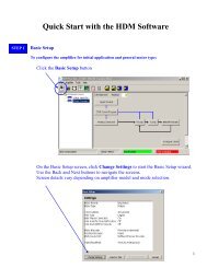
Chapter 6Setting up parameters<br />
[Monitor <strong>mode</strong>]<br />
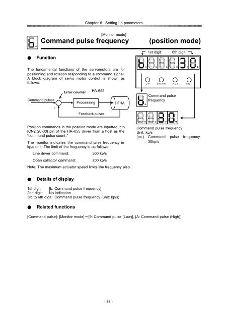
Command pulse frequency<br />
(<strong>position</strong> <strong>mode</strong>)<br />
Function<br />
1st digit<br />
6th digit<br />
The fundamental functions of the servomotors are for<br />
<strong>position</strong>ing and rotation responding to a command signal.<br />
A block diagram of servo motor control is shown as<br />
follows:<br />
U P D O W N A D J S E T<br />
Command pulse+<br />
-<br />
Error counter HA-655<br />
Processing<br />
FHA<br />
Command pulse<br />
frequency<br />
Feedback pulses<br />
Position commands in the <strong>position</strong> <strong>mode</strong> are inputted into<br />
[CN2 26-30] pin of the HA-655 driver from a host as the<br />
“command pulse count.”<br />
The monitor indicates the command pulse frequency in<br />
kp/s unit. The limit of the frequency is as follows:<br />
Line driver command:<br />
Open collector command:<br />
500 kp/s<br />
200 kp/s<br />
Note: The maximum actuator <strong>speed</strong> limits the frequency also.<br />
Command pulse frequency<br />
Unit: kp/s<br />
(ex.) Command pulse frequency<br />
= 30kp/s<br />
Details of display<br />
1st digit: [b: Command pulse frequency]<br />
2nd digit: No indication<br />
3rd to 6th digit: Command pulse frequency (unit: kp/s)<br />
Related functions<br />
[Command pulse]: [Monitor <strong>mode</strong>][9: Command pulse (Low)], [A: Command pulse (High)]<br />
- 88 -