position / speed mode - Harmonic Drive LLC
position / speed mode - Harmonic Drive LLC
position / speed mode - Harmonic Drive LLC

Create successful ePaper yourself
Turn your PDF publications into a flip-book with our unique Google optimized e-Paper software.
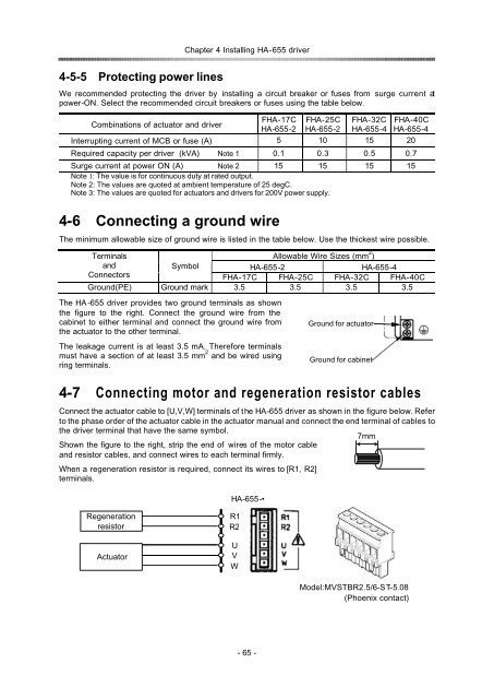
Chapter 4 Installing HA-655 driver<br />
4-5-5Protecting power lines<br />
We recommended protecting the driver by installing a circuit breaker or fuses from surge current at<br />
power-ON. Select the recommended circuit breakers or fuses using the table below.<br />
FHA-17C FHA-25C FHA-32C FHA-40C<br />
Combinations of actuator and driver<br />
HA-655-2 HA-655-2 HA-655-4 HA-655-4<br />
Interrupting current of MCB or fuse (A) 5 10 15 20<br />
Required capacity per driver (kVA) Note 1 0.1 0.3 0.5 0.7<br />
Surge current at power ON (A) Note 2 15 15 15 15<br />
Note 1: The value is for continuous duty at rated output.<br />
Note 2: The values are quoted at ambient temperature of 25 degC.<br />
Note 3: The values are quoted for actuators and drivers for 200V power supply.<br />
4-6Connecting a ground wire<br />
The minimum allowable size of ground wire is listed in the table below. Use the thickest wire possible.<br />
Terminals<br />
Allowable Wire Sizes (mm 2 )<br />
and<br />
Symbol<br />
HA-655-2<br />
HA-655-4<br />
Connectors<br />
FHA-17C FHA-25C FHA-32C FHA-40C<br />
Ground(PE) Ground mark 3.5 3.5 3.5 3.5<br />
The HA -655 driver provides two ground terminals as shown<br />
the figure to the right. Connect the ground wire from the<br />
cabinet to either terminal and connect the ground wire from<br />
the actuator to the other terminal.<br />
The leakage current is at least 3.5 mA. Therefore terminals<br />
must have a section of at least 3.5 mm 2 and be wired using<br />
ring terminals.<br />
4-7Connecting motor and regeneration resistor cables<br />
Connect the actuator cable to [U,V,W] terminals of the HA-655 driver as shown in the figure below. Refer<br />
to the phase order of the actuator cable in the actuator manual and connect the end terminal of cables to<br />
the driver terminal that have the same symbol.<br />
Shown the figure to the right, strip the end of wires of the motor cable<br />
and resistor cables, and connect wires to each terminal firmly.<br />
When a regeneration resistor is required, connect its wires to [R1, R2]<br />
terminals.<br />
HA-655-•<br />
Ground for actuator<br />
Ground for cabinet<br />
7mm<br />
Regeneration<br />
resistor<br />
Actuator<br />
R1<br />
R2<br />
U<br />
V<br />
W<br />
Model:MVSTBR2.5/6-ST-5.08<br />
(Phoenix contact)<br />
- 65 -