position / speed mode - Harmonic Drive LLC
position / speed mode - Harmonic Drive LLC
position / speed mode - Harmonic Drive LLC

Create successful ePaper yourself
Turn your PDF publications into a flip-book with our unique Google optimized e-Paper software.
2-2Position <strong>mode</strong><br />
Chapter 2Functions<br />
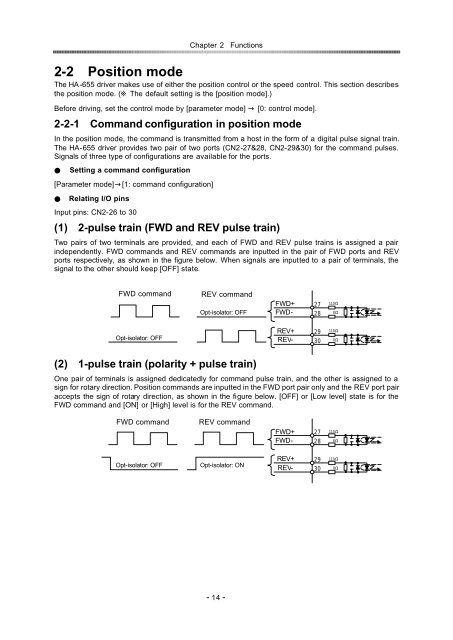
The HA -655 driver makes use of either the <strong>position</strong> control or the <strong>speed</strong> control. This section describes<br />
the <strong>position</strong> <strong>mode</strong>. ( The default setting is the [<strong>position</strong> <strong>mode</strong>].)<br />
Before driving, set the control <strong>mode</strong> by [parameter <strong>mode</strong>] [0: control <strong>mode</strong>].<br />
2-2-1Command configuration in <strong>position</strong> <strong>mode</strong><br />
In the <strong>position</strong> <strong>mode</strong>, the command is transmitted from a host in the form of a digital pulse signal train.<br />
The HA-655 driver provides two pair of two ports (CN2-27&28, CN2-29&30) for the command pulses.<br />
Signals of three type of configurations are available for the ports.<br />
Setting a command configuration<br />
[Parameter <strong>mode</strong>][1: command configuration]<br />
Relating I/O pins<br />
Input pins: CN2-26 to 30<br />
(1)2-pulse train (FWD and REV pulse train)<br />
Two pairs of two terminals are provided, and each of FWD and REV pulse trains is assigned a pair<br />
independently. FWD commands and REV commands are inputted in the pair of FWD ports and REV<br />
ports respectively, as shown in the figure below. When signals are inputted to a pair of terminals, the<br />
signal to the other should keep [OFF] state.<br />
FWD command<br />
REV command<br />
Opt-isolator: OFF<br />
FWD+<br />
FWD-<br />
<br />
<br />
<br />
<br />
Opt-isolator: OFF<br />
REV+<br />
REV-<br />
<br />
<br />
<br />
<br />
(2)1-pulse train (polarity + pulse train)<br />
One pair of terminals is assigned dedicatedly for command pulse train, and the other is assigned to a<br />
sign for rotary direction. Position commands are inputted in the FWD port pair only and the REV port pair<br />
accepts the sign of rotary direction, as shown in the figure below. [OFF] or [Low level] state is for the<br />
FWD command and [ON] or [High] level is for the REV command.<br />
FWD command<br />
REV command<br />
FWD+<br />
FWD-<br />
<br />
<br />
<br />
<br />
Opt-isolator: OFF<br />
Opt-isolator: ON<br />
REV+<br />
REV-<br />
<br />
<br />
<br />
<br />
- 14 -