AJA FS1 Installation and Operation Guide
AJA FS1 Installation and Operation Guide
AJA FS1 Installation and Operation Guide

Create successful ePaper yourself
Turn your PDF publications into a flip-book with our unique Google optimized e-Paper software.
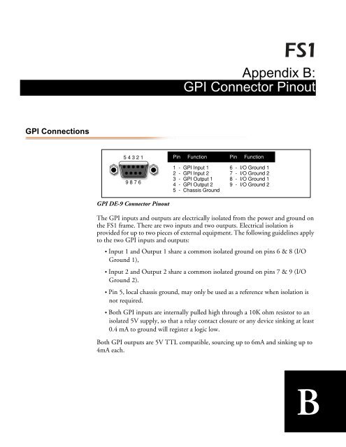
GPI Connections<br />
5 4 3 2 1<br />
9 8 7 6<br />
GPI DE-9 Connector Pinout<br />
Appendix B:<br />
GPI Connector Pinout<br />
Pin Function<br />
1 - GPI Input 1<br />
2 - GPI Input 2<br />
3 - GPI Output 1<br />
4 - GPI Output 2<br />
5 - Chassis Ground<br />
Pin Function<br />
6 - I/O Ground 1<br />
7 - I/O Ground 2<br />
8 - I/O Ground 1<br />
9 - I/O Ground 2<br />
The GPI inputs <strong>and</strong> outputs are electrically isolated from the power <strong>and</strong> ground on<br />
the <strong>FS1</strong> frame. There are two inputs <strong>and</strong> two outputs. Electrical isolation is<br />
provided for up to two pieces of external equipment. The following guidelines apply<br />
to the two GPI inputs <strong>and</strong> outputs:<br />
• Input 1 <strong>and</strong> Output 1 share a common isolated ground on pins 6 & 8 (I/O<br />
Ground 1),<br />
• Input 2 <strong>and</strong> Output 2 share a common isolated ground on pins 7 & 9 (I/O<br />
Ground 2).<br />
• Pin 5, local chassis ground, may only be used as a reference when isolation is<br />
not required.<br />
• Both GPI inputs are internally pulled high through a 10K ohm resistor to an<br />
isolated 5V supply, so that a relay contact closure or any device sinking at least<br />
0.4 mA to ground will register a logic low.<br />
Both GPI outputs are 5V TTL compatible, sourcing up to 6mA <strong>and</strong> sinking up to<br />
4mA each.<br />
B1