- Page 1 and 2:
B e c a u s e i t m a t t e r s . w
- Page 3:
Limited Warranty Important Safety I
- Page 6 and 7:
vi Reference Video (looping). . . .
- Page 8 and 9:
viii 21.2 Audio Phase Ch2 . . . . .
- Page 10 and 11:
x Canadian ICES Statement . . . . .
- Page 12 and 13:
2 FS1 Front Panel Control • HD cr
- Page 14 and 15:
4 w/Embedded Audio Analog Audio Inp
- Page 17 and 18:
Controls and Indicators Chapter 2:
- Page 19 and 20:
FS1 Installation and Operation Manu
- Page 21 and 22:
FS1 Installation and Operation Manu
- Page 23 and 24:
About Video and Format Compatibilit
- Page 25 and 26:
Connector Descriptions • 10/100 L
- Page 27:
FS1 Installation and Operation Manu
- Page 30 and 31:
20 Warning! To meet safety regulati
- Page 32 and 33:
22 Unpacking Shipping Box Contents
- Page 34 and 35:
24 Networking the FS1 via DHCP The
- Page 36 and 37:
26 Networking the FS1 using the Fac
- Page 38 and 39:
28 Uploading and Installing the Sof
- Page 40 and 41:
30 Power Requirements System Video/
- Page 42 and 43:
32 RP-155), so the +24 dBu setting
- Page 44 and 45:
34 Pressing either a parameter Sele
- Page 46 and 47:
36 1.3 Component Out This parameter
- Page 48 and 49:
38 2.11 Audio Map Ch1 This paramete
- Page 50 and 51:
40 2.21 Audio Map Ch 1/2 This param
- Page 52 and 53:
42 3.4 NTSC Standard 4.1 Analog Aud
- Page 54 and 55:
44 4.5 Audio Follow Video 4.6 AFV M
- Page 56 and 57:
46 5.2 Downconvert Mode This parame
- Page 58 and 59:
48 5.3 SD Aspect Ratio Convert This
- Page 60 and 61:
50 5.6 AFD Out SDI 1 5.7 AFD Out SD
- Page 62 and 63:
52 6.4 Analog Output Fine (Horizont
- Page 64 and 65:
54 10.2 Proc Amp Gain 10.3 Proc Amp
- Page 66 and 67:
56 20.2 Audio Level Ch2 20.3 Audio
- Page 68 and 69: 58 21.5 Audio Phase Ch5 21.6 Audio
- Page 70 and 71: 60 31.1 Upconvert Line 21 31.1 Upco
- Page 72 and 73: 62 36.1 GPI IN 1 Response The setti
- Page 74 and 75: 64 37.1 GPI 1 OUT 37.2 GPI 2 OUT Th
- Page 76 and 77: 66 50.1 IP Config 50.2 IP Address T
- Page 78 and 79: 68 50.5 System Name 50.6 MAC Addres
- Page 80 and 81: 70 51.3 SNMP Trap Port 1 This param
- Page 82 and 83: 72 60.2 Format Alarm 60.3 Reference
- Page 84 and 85: 74 91.1 Preset Recall 92.1 Preset S
- Page 87 and 88: Remote FS1 Control Via a Web Browse
- Page 89 and 90: Resetting Values To Factory Setting
- Page 91 and 92: Embed Audio Out (4.3) On (default)
- Page 93 and 94: Audio Control Screen FS1 Installati
- Page 95 and 96: Convert Mode Screen Stereo Map Chan
- Page 97 and 98: AFD Out SDI1 (5.6) Off (Default) Au
- Page 99 and 100: ProcAmp Control Screen FS1 Installa
- Page 101 and 102: FS1 Installation and Operation Manu
- Page 103 and 104: Miscellaneous Screen FS1 Installati
- Page 105 and 106: No Action (default) Freeze FS1 Inst
- Page 107 and 108: FS1 Installation and Operation Manu
- Page 109 and 110: Test Signals Screen FS1 Installatio
- Page 111 and 112: FS1 Installation and Operation Manu
- Page 113 and 114: FS1 Simple Network Management Proto
- Page 115 and 116: Formats 525i 625i 1080i 50/59.94/60
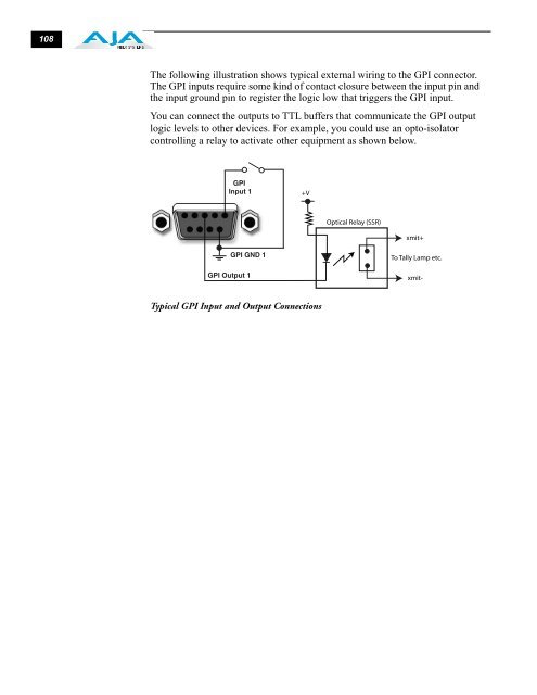
- Page 117: GPI Connections 5 4 3 2 1 9 8 7 6 G
- Page 121 and 122: Federal Communications Commission (
- Page 124 and 125: 114 Before Operating Your FS1 Unit,
- Page 126 and 127: 116 Attenzione! Questo dispositivo
- Page 128 and 129: 118 Avviso! Proteggere il cavo di a
- Page 130 and 131: 120 16:9 Refers to the aspect ratio
- Page 132 and 133: 122 Processing Amplifier (Proc Amp)
- Page 134 and 135: 124 C Cable Connections 7, 30 Cabli
- Page 136 and 137: 126 1.3 Component Out 36 10.1 Proc
- Page 138: 128 Video Format Status 9 Video In