AJA FS1 Installation and Operation Guide
AJA FS1 Installation and Operation Guide
AJA FS1 Installation and Operation Guide

Create successful ePaper yourself
Turn your PDF publications into a flip-book with our unique Google optimized e-Paper software.
12<br />
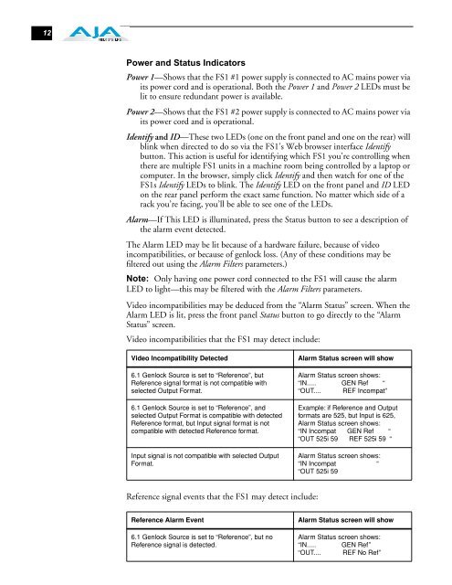
Power <strong>and</strong> Status Indicators<br />
Power 1—Shows that the <strong>FS1</strong> #1 power supply is connected to AC mains power via<br />
its power cord <strong>and</strong> is operational. Both the Power 1 <strong>and</strong> Power 2 LEDs must be<br />
lit to ensure redundant power is available.<br />
Power 2—Shows that the <strong>FS1</strong> #2 power supply is connected to AC mains power via<br />
its power cord <strong>and</strong> is operational.<br />
Identify <strong>and</strong> ID—These two LEDs (one on the front panel <strong>and</strong> one on the rear) will<br />
blink when directed to do so via the <strong>FS1</strong>’s Web browser interface Identify<br />
button. This action is useful for identifying which <strong>FS1</strong> you’re controlling when<br />
there are multiple <strong>FS1</strong> units in a machine room being controlled by a laptop or<br />
computer. In the browser, simply click Identify <strong>and</strong> then watch for one of the<br />
<strong>FS1</strong>s Identify LEDs to blink. The Identify LED on the front panel <strong>and</strong> ID LED<br />
on the rear panel perform the exact same function. No matter which side of a<br />
rack you’re facing, you’ll be able to see one of the LEDs.<br />
Alarm—If This LED is illuminated, press the Status button to see a description of<br />
the alarm event detected.<br />
The Alarm LED may be lit because of a hardware failure, because of video<br />
incompatibilities, or because of genlock loss. (Any of these conditions may be<br />
filtered out using the Alarm Filters parameters.)<br />
Note: Only having one power cord connected to the <strong>FS1</strong> will cause the alarm<br />
LED to light—this may be filtered with the Alarm Filters parameters.<br />
Video incompatibilities may be deduced from the “Alarm Status” screen. When the<br />
Alarm LED is lit, press the front panel Status button to go directly to the “Alarm<br />
Status” screen.<br />
Video incompatibilities that the <strong>FS1</strong> may detect include:<br />
Video Incompatibility Detected Alarm Status screen will show<br />
6.1 Genlock Source is set to “Reference”, but<br />
Reference signal format is not compatible with<br />
selected Output Format.<br />
6.1 Genlock Source is set to “Reference”, <strong>and</strong><br />
selected Output Format is compatible with detected<br />
Reference format, but Input signal format is not<br />
compatible with detected Reference format.<br />
Input signal is not compatible with selected Output<br />
Format.<br />
Reference signal events that the <strong>FS1</strong> may detect include:<br />
Alarm Status screen shows:<br />
“IN..... GEN Ref “<br />
“OUT.... REF Incompat”<br />
Example: if Reference <strong>and</strong> Output<br />
formats are 525, but Input is 625,<br />
Alarm Status screen shows:<br />
“IN Incompat GEN Ref “<br />
“OUT 525i 59 REF 525i 59 “<br />
Alarm Status screen shows:<br />
“IN Incompat “<br />
“OUT 525i 59<br />
Reference Alarm Event Alarm Status screen will show<br />
6.1 Genlock Source is set to “Reference”, but no<br />
Reference signal is detected.<br />
Alarm Status screen shows:<br />
“IN..... GEN Ref”<br />
“OUT.... REF No Ref”