- Page 1 and 2:
SERVICE MANUALSERVICE MANUAL
- Page 3 and 4:
CONTENTSFIGURESXIGETTING STARTED 1-
- Page 5 and 6:
ContentsSERVICING STANDARD MORTISE
- Page 7 and 8:
ContentsServicing the cylinder 8-10
- Page 9 and 10:
ContentsServicing the yoke 10-20Rem
- Page 11 and 12:
FIGURESGETTING STARTEDSystem overvi
- Page 13 and 14:
FiguresRemoving the inside rose lin
- Page 15 and 16:
FiguresB.A.S.I.S. Transport Diagnos
- Page 17 and 18:
1 GETTING STARTEDINTRODUCTIONThe B.
- Page 19 and 20:
Getting StartedPersonal computer ru
- Page 21 and 22:
Getting StartedCERTIFICATIONS AND S
- Page 23 and 24:
Getting StartedDocument TitleG09 In
- Page 25 and 26:
2 STANDARD FUNCTIONS ANDPARTSThe fo
- Page 27 and 28:
Standard Functions and PartsLV-Dead
- Page 29 and 30: B.A.S.I.S. G Service Manual 2-5TRIM
- Page 31 and 32: Standard Functions and PartsItem Pa
- Page 33 and 34: Standard Functions and PartsSmart c
- Page 35 and 36: B.A.S.I.S. G Service Manual 2-11DUA
- Page 37 and 38: Standard Functions and PartsItem Pa
- Page 39 and 40: Standard Functions and PartsMortise
- Page 41 and 42: Standard Functions and PartsOther m
- Page 43 and 44: Standard Functions and PartsCylindr
- Page 45 and 46: 3 EXIT HARDWARE TRIMFUNCTIONS AND P
- Page 47 and 48: B.A.S.I.S. G Service Manual 3-3TRIM
- Page 49 and 50: Exit Hardware Trim Functions and Pa
- Page 51 and 52: Exit Hardware Trim Functions and Pa
- Page 53 and 54: B.A.S.I.S. G Service Manual 3-9DUAL
- Page 55 and 56: Exit Hardware Trim Functions and Pa
- Page 57 and 58: Exit Hardware Trim Functions and Pa
- Page 59 and 60: 4 SHARED STANDARD AND EXITHARDWARE
- Page 61 and 62: Shared Standard and Exit Hardware T
- Page 63 and 64: Shared Standard and Exit Hardware T
- Page 65 and 66: Shared Standard and Exit Hardware T
- Page 67 and 68: Shared Standard and Exit Hardware T
- Page 69 and 70: OTHER SYSTEM COMPONENTSOther system
- Page 71 and 72: 5 SERVICING STANDARDMORTISE TRIM PA
- Page 73 and 74: Servicing Standard Mortise Trim Par
- Page 75 and 76: Servicing Standard Mortise Trim Par
- Page 77 and 78: Servicing Standard Mortise Trim Par
- Page 79: Servicing Standard Mortise Trim Par
- Page 83 and 84: Servicing Standard Mortise Trim Par
- Page 85 and 86: Servicing Standard Mortise Trim Par
- Page 87 and 88: Servicing Standard Mortise Trim Par
- Page 89 and 90: 6 SERVICING STANDARDMORTISE CASE PA
- Page 91 and 92: Servicing Standard Mortise Case Par
- Page 93 and 94: Servicing Standard Mortise Case Par
- Page 95 and 96: Servicing Standard Mortise Case Par
- Page 97 and 98: Servicing Standard Mortise Case Par
- Page 99 and 100: Servicing Standard Mortise Case Par
- Page 101 and 102: Servicing Standard Mortise Case Par
- Page 103 and 104: Servicing Standard Mortise Case Par
- Page 105 and 106: Servicing Standard Mortise Case Par
- Page 107 and 108: Servicing Standard Mortise Case Par
- Page 109 and 110: 7 SERVICING CYLINDRICAL PARTSThis c
- Page 111 and 112: Servicing Cylindrical PartsSERVICIN
- Page 113 and 114: Servicing Cylindrical PartsSERVICIN
- Page 115 and 116: Servicing Cylindrical Partsb. Remov
- Page 117 and 118: Servicing Cylindrical Parts2. Insta
- Page 119 and 120: Servicing Cylindrical Parts4. Conne
- Page 121 and 122: Servicing Cylindrical PartsCautionC
- Page 123 and 124: Servicing Cylindrical PartsSERVICIN
- Page 125 and 126: Servicing Cylindrical Parts6. Tight
- Page 127 and 128: 8 SERVICING EXIT HARDWARETRIM PARTS
- Page 129 and 130: Servicing Exit Hardware Trim PartsR
- Page 131 and 132:
Servicing Exit Hardware Trim PartsR
- Page 133 and 134:
Servicing Exit Hardware Trim PartsR
- Page 135 and 136:
Servicing Exit Hardware Trim PartsS
- Page 137 and 138:
Servicing Exit Hardware Trim PartsR
- Page 139 and 140:
Servicing Exit Hardware Trim PartsS
- Page 141 and 142:
9 SERVICING STANDARDOUTSIDE ESCUTCH
- Page 143 and 144:
Servicing Standard Outside Escutche
- Page 145 and 146:
Servicing Standard Outside Escutche
- Page 147 and 148:
Servicing Standard Outside Escutche
- Page 149 and 150:
Servicing Standard Outside Escutche
- Page 151 and 152:
Servicing Standard Outside Escutche
- Page 153 and 154:
Servicing Standard Outside Escutche
- Page 155 and 156:
Servicing Standard Outside Escutche
- Page 157 and 158:
Servicing Standard Outside Escutche
- Page 159 and 160:
Servicing Standard Outside Escutche
- Page 161 and 162:
Servicing Standard Outside Escutche
- Page 163 and 164:
Servicing Standard Outside Escutche
- Page 165 and 166:
Servicing Standard Outside Escutche
- Page 167 and 168:
10 SERVICING EXIT HARDWARETRIM ESCU
- Page 169 and 170:
Servicing Exit Hardware Trim Escutc
- Page 171 and 172:
Servicing Exit Hardware Trim Escutc
- Page 173 and 174:
Servicing Exit Hardware Trim Escutc
- Page 175 and 176:
Servicing Exit Hardware Trim Escutc
- Page 177 and 178:
Servicing Exit Hardware Trim Escutc
- Page 179 and 180:
Servicing Exit Hardware Trim Escutc
- Page 181 and 182:
Servicing Exit Hardware Trim Escutc
- Page 183 and 184:
Servicing Exit Hardware Trim Escutc
- Page 185 and 186:
Servicing Exit Hardware Trim Escutc
- Page 187 and 188:
Servicing Exit Hardware Trim Escutc
- Page 189 and 190:
Servicing Exit Hardware Trim Escutc
- Page 191 and 192:
Servicing Exit Hardware Trim Escutc
- Page 193 and 194:
Servicing Exit Hardware Trim Escutc
- Page 195 and 196:
Servicing Exit Hardware Trim Escutc
- Page 197 and 198:
11 MAINTENANCEThis chapter includes
- Page 199 and 200:
MaintenanceReinstalling thebackup b
- Page 201 and 202:
MaintenanceInside escutcheonBattery
- Page 203 and 204:
Maintenance4. Use a T15 TORX bit dr
- Page 205 and 206:
MaintenanceReinstalling thebattery
- Page 207 and 208:
Maintenance6. For B.A.S.I.S. mortis
- Page 209 and 210:
MaintenancePERFORMING DIAGNOSTICS U
- Page 211 and 212:
MaintenancePDASerial cableCommunica
- Page 213 and 214:
MaintenanceNote: To perform other a
- Page 215 and 216:
MaintenanceUnlocking a doortemporar
- Page 217 and 218:
12 TROUBLESHOOTINGThis chapter cont
- Page 219 and 220:
TroubleshootingENABLING COMMUNICATI
- Page 221 and 222:
Troubleshooting8. For standard lock
- Page 223 and 224:
TroubleshootingRESPONDING TO PROBLE
- Page 225 and 226:
TroubleshootingLEDs Sounder Access
- Page 227 and 228:
TroubleshootingWhen communicatingbe
- Page 229 and 230:
A LOCK HISTORY EVENT TYPESThe follo
- Page 231 and 232:
Lock History Event TypesEventREADER
- Page 233 and 234:
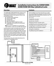
B INSTALLATION INSTRUCTIONSThe foll
- Page 235 and 236:
Planning the installationContentsTh
- Page 237 and 238:
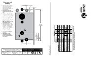
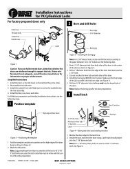
Preparing the door and door jamb3 M
- Page 239 and 240:
Preparing the door and door jambIns
- Page 241 and 242:
Installing the lock9 Install core (
- Page 243 and 244:
Installing the lockInstallation Ins
- Page 245 and 246:
Installing the lockInstallation Ins
- Page 247 and 248:
Completing the installationInstalla
- Page 249 and 250:
Completing the installation20 Test
- Page 251 and 252:
Planning the installationInstallati
- Page 253 and 254:
Preparing the door and door jambIns
- Page 255 and 256:
Preparing the door and door jambIns
- Page 257 and 258:
Installing the lockInstallation Ins
- Page 259 and 260:
Installing the lock13 Make motor co
- Page 261 and 262:
Completing the installation17 Insta
- Page 263 and 264:
Planning the installationContentsTh
- Page 265 and 266:
Preparing the doorInstallation Inst
- Page 267 and 268:
Preparing the doorInstallation Inst
- Page 269 and 270:
Installing the exit hardware and tr
- Page 271 and 272:
Installing the exit hardware and tr
- Page 273 and 274:
Completing the installationInstalla
- Page 275 and 276:
C INDEXAadding key override sensing
- Page 277 and 278:
IndexLlatch 2-20latch leverpart dra
- Page 279 and 280:
Indextechnical documentation packag


![B.A.S.I.S. G Service Manual [T63300] - Best Access Systems](https://img.yumpu.com/48375082/80/500x640/basis-g-service-manual-t63300-best-access-systems.jpg)