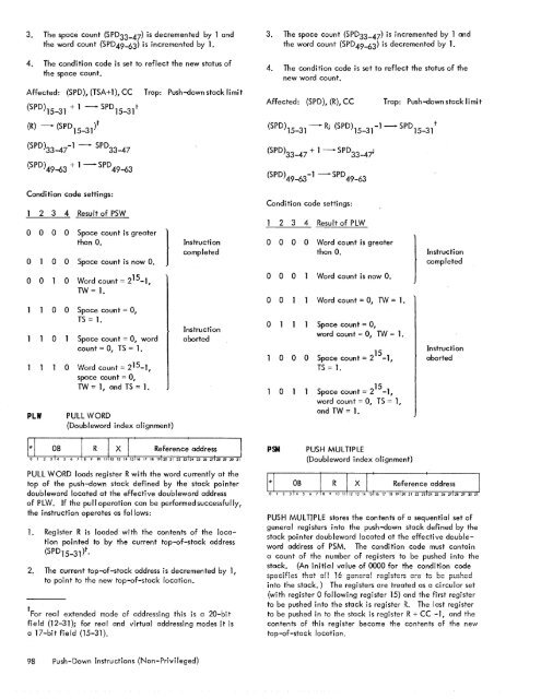
3. <strong>The</strong> space count (SPD33-47) is decremented by 1 andthe word count (SPD49-63) is incremented by <strong>1.</strong>4. <strong>The</strong> condition code is set to reflect the new status ofthe space count.Affected: (SPD), (TSA+1), CC(SPD)15_31 + 1 -SPD 15_ 31tTrap: Push-down stack limit3. <strong>The</strong> space count (SPD33-47) is incremented by 1 andthe word count (SPD49-63) is decremented by <strong>1.</strong>4. <strong>The</strong> condition code is set to reflect the status of thenew word count.Affected: (SPD), (R), CCTrap: Push-down stack limit(R) - (SPD 15_ 31)t(SPD)15_31- R; (SPD)15_31-1 -SPD 15_ 31t(SPD)33_47-1 - SPD 33_ 47{SPD)33_47 + 1 -SPD 33_ 4i(SPD) 49-63 + 1 - SPD 49-63Condi ti on code setti ngs:2 3 4 Result of PSW0 0 0 0 Space count is greaterthan O.0 0 0 Space count is now O.0 0 0 Word count = 2 15 _1 ,TW = <strong>1.</strong>PLW0 0 Space count = 0,TS = <strong>1.</strong>0 Space count = 0, wordcount = 0, TS = <strong>1.</strong>0 Word count = 2 15 _1 ,space count = 0,TW = 1, and TS = <strong>1.</strong>}PULL WORD(Doubleword index alignment)08 I R I x I 1Instructi oncompletedInstructionabortedReference address Io 1 2 3 14 5 718 9 10 llL2 13 14'15h6 17 18 19120 21 22 231242526 2712829 JO )PULL WORD loads register R with the word currently at thetop of the push-down stack defined by the stack pointerdoubleword located at the effective doubleword addressof PLW. If the pull operation can be performed successfully,the instruction operates as follows:<strong>1.</strong> Register R is loaded with the contents of the locationpointed to by the current top-of-stack address(SPD 1 5_31)t.2. <strong>The</strong> current top-of-stack address is decremented by 1,to point to the new top-of-stack location.tFor real extended mode of addressing this is a 20-bitfield (12-31); for real and virtual addressing modes it isa 17-bit field (15-31).(SPD)49_63-1 -SPD 49-63Condition code settings:2 3 4 Result of PLW0 0 0 0 Word count is greaterthan O.0 0 0 Word count is now O.0 0 Word count = 0, TW = <strong>1.</strong>0 Space count = 0,word count = 0, TW = <strong>1.</strong>PSM0 0 00 115Space count = 2 -1,TS = <strong>1.</strong>15Space count = 2 -1,word count = 0, TS = 1,and TW = <strong>1.</strong>PUSH MULTIPLE(Doubleword index alignment)) InstructioncompletedInstructionabortedPUSH MULTIPLE stores the contents of a sequential set ofgeneral registers into the push-down stack defined by thestack pointer doubleword located at the effective doublewordaddress of PSM. <strong>The</strong> condition code must containa count of the number of registers to be pushed into thestack. (An initial value of 0000 for the condition codespecifics that ef! 16 genera! registers ere to be pushedinto the stack.) <strong>The</strong> registers are treated as a circular set(with register 0 following register 15) and the first registerto be pushed into the stack is register R. <strong>The</strong> last registerto be pushed in to the stack is register R + CC -1, and thecontents of this register become the contents of the newtop-of-stack location.98 Push-Down Instructions (Non-Privileged)
If there is sufficient space in the stack for all of thespecified registers, PSM operates as follows:<strong>1.</strong> <strong>The</strong> contents of registers R to R = CC - 1 are stored inascending sequence, beginning with the locationtion pointed to by the current top-of-stack address(SPD15_31)t plus 1 and ending with the current topof-stackaddress plus CC.2. <strong>The</strong> current top-of-stack address is incremented by thevalue of CC, to point to the new top-of-stack location.3. <strong>The</strong> space count (SPD33-47) is decremented by thevalue of CC and the word count is incremented by thevalue of CC.4. <strong>The</strong> condition code is set to reflect the new status ofthe space count.Affected: (SPD), (TSA+1) to(TSA+CC), CCTrap: Push-down stack limit(R) - (SPD)15_31 + <strong>1.</strong> .. (R+CC-l) - (SPD)t 15-31 + CC(SPD)15_ 31+CC -SPD 15_ 3/(SPD)33_47-CC -SPD 33_ 47(SPD) 49-63 +CC - SPD 49-63Condition code settings:0002 3 4 Result of PSM0 0 00 00 00 0 0Space count> o.Space count = O.Word count + CC > 2 15 _1,TW = <strong>1.</strong>Space count < CC, TS = <strong>1.</strong>InstructioncompletedIf the instruction operation extends into a memory pageprotected either by the access protection codes or writelocks, the memory protection trap can occur. If the operationextends into a memory region"that is physically notpresent, the nonexistent memory address trap can occur.If the address of the elements within the stack (pointed toby the top-of-stack address) is in the range 0 through -15,then the registers indi cated by the R field of the PSM instructionare stored in the general registers rather than inmain memory. In this case the results wi II be unpredictable ifany source registers are also used as destination registers.PLMPULL MULTIPLE(Doubleword index alignment)PULL MULTIPLE loads a sequential set of general registersfrom the push-down stack defined by the stack pointerdoubleword located at the effective doubleword address ofPLM. <strong>The</strong> condition code must contain a count of the numberof words to be pulled from the stack. (An initiaJ valueof 0000 for the condition code specifies that 16 words areto be pulled from the stack.) <strong>The</strong> registers are treated as acircular set (with register 0 following register 15), the firstregister to be loaded from the stack is register R+CC-1, andthe contents of the current top-of-stack location becomesthe contents of this register. <strong>The</strong> last register to be loadedis register R.If there is a sufficient number of words in the stack to loadall of the specified registers, PLM operates as toiiows:<strong>1.</strong> Registers R+CC-1 to register R are loaded in descendingsequence, beginning with the contents of the locationpointed to by the current top-of-stack address(SPD15-31)t and ending with the contents of the locationpointed to by the current top-of-stack addressminus CC-<strong>1.</strong>o 0Space count < CC, worqcount = 0, TS = <strong>1.</strong>2. <strong>The</strong> current top-of-stack address is decremented by thevalue of CC, to point to the new" top-of-stack location.0 0Space count < CC, wordcount + CC > 215_1TS = 1, and TW = <strong>1.</strong>Instructi onaborted3. <strong>The</strong> space count (SPD33-47) is incremented by thevalue of CC and the word count is decremented by thevalue of CC.0 000Space count = 0, TS = <strong>1.</strong>Space count = 0, wordcount = 0, TS = <strong>1.</strong>Space count = 0, wordcount + CC > 215_1,TS = 1, and TW = <strong>1.</strong>tFor real extended mode of addressing this is a 20-bitfield (12-31); for real and virtual addressing modes it is a17-bit field (15-31).4. <strong>The</strong> condition code is set to reflect the new status ofthe word count.Affected: (SPD), (R+CC-l)to (R), CC((SPDh5_31t-R +CC -1, ... ,((SPD)15-31 -Icc - 11) - Rt(SPD)15-31 - CC- SPD 15-31 t(SPD)33-47 + CC - SPD33-47(SPD)49-63 - CC - SPD49-63Trap: Push-down stack limitpush-Down Instructions (Non-Privileged) 99
- Page 1 and 2:
Xerox 560 ComputerReference Manual9
- Page 5 and 6:
4. INPUT/OUTPUT OPERA TIO NS 142 AG
- Page 7 and 8:
1. XEROX 560 COMPUTER SYSTEMINTRODU
- Page 10 and 11:
Many operations are performed in fl
- Page 12 and 13:
Rapid Context Switching. When respo
- Page 14 and 15:
2. SYSTEM ORGANIZATIONThe elements
- Page 16:
FAST MEMORYARITHMETIC AND CONTROL U
- Page 19 and 20:
INFORMATION BOUNDARIESBasic process
- Page 21 and 22:
(Maximumof eight)Core Core Core Cor
- Page 23 and 24:
3. Diagnostic logic. Each memory dr
- Page 25 and 26:
eference address field of the instr
- Page 27 and 28:
Instruction in memory:Instruction i
- Page 29 and 30:
Real-extended addressing is specifi
- Page 31:
Table 1. Basic Processor Operating
- Page 35 and 36:
DesignationFunctionDesignationFunct
- Page 37 and 38:
InterruptStateDisarmedArmed[$Waitin
- Page 39 and 40:
AddressTable 2. Interrupt Locations
- Page 41 and 42:
is assumed to contain an XPSD or a
- Page 43 and 44:
Table 3. Summary of Trap LocationsL
- Page 45 and 46:
TRAP MASKSThe programmer may mask t
- Page 47 and 48:
PUSH-DOWN STACK LIMIT TRAPPush-down
- Page 49 and 50:
Instruction Name Mnemonic FaultDeci
- Page 51 and 52:
subroutine. However, with certain c
- Page 53 and 54: 3. INSTRUCTION REPERTOIREThis chapt
- Page 55 and 56: CC1 is unchanged by the instruction
- Page 57 and 58: Condition code settings:2 3 4 Resul
- Page 59 and 60: Example 2, odd R field value:Before
- Page 61 and 62: significance (FS), floating zero (F
- Page 63 and 64: next sequential register after regi
- Page 65 and 66: R 1 R2 R3 MeaningoThe effective vir
- Page 67 and 68: Condition code settings:2 3 4 Resul
- Page 69 and 70: MIMULTIPLY IMMEDIATE(Immediate oper
- Page 71 and 72: original contents of register R, re
- Page 73 and 74: Instruction NameCompare HalfwordMne
- Page 75 and 76: Condition code settings:2 3 4 Resul
- Page 77 and 78: 2 3 4 Result of ShiftCircular Shift
- Page 79 and 80: 4. At the completion of the left sh
- Page 81 and 82: Instruction NameFloating Subtract L
- Page 83 and 84: The following table shows the possi
- Page 85 and 86: Table 8.Condition Code Settings for
- Page 87 and 88: PACKED DECIMAL NUMBERSAll decimal a
- Page 89 and 90: DSTDECIMAL STORE(Byte index alignme
- Page 91 and 92: If no indirect addressing or indexi
- Page 93 and 94: Instruction NameMnemonicDesignation
- Page 95 and 96: Both byte strings are C bytes in le
- Page 97 and 98: of the destination byte that caused
- Page 99 and 100: again present, unti I a positive or
- Page 101 and 102: The new contents of register 7 are:
- Page 103: traps to location X'42 1 as a resul
- Page 107 and 108: If CC1, or CC3, or both CC1 and CC3
- Page 109 and 110: appropriate memory stack locations
- Page 111 and 112: II, EI) are generated by II ORing"
- Page 113 and 114: In the real extended addressing mod
- Page 115 and 116: CAll INSTRUCTIONSEach ofthe four CA
- Page 117 and 118: The XPSD instruction' is used for t
- Page 119 and 120: If (I)1O = 0, trap or interrupt ins
- Page 121 and 122: For either memory map format and ei
- Page 123 and 124: initial value plus the initial valu
- Page 125 and 126: Table 9. Status Word 0Field Bits Co
- Page 127 and 128: READ INTERRUPT INHIBITSThe followin
- Page 129 and 130: Table 11.Read Direct Mode 9 Status
- Page 131 and 132: SET ALARM INDICATORThe following co
- Page 133 and 134: INPUT jOUTPUT INSTRUCTIONSThe I/o i
- Page 135 and 136: Table 13.Description of I/o Instruc
- Page 137 and 138: Table 15.Device Status Byte (Regist
- Page 139 and 140: Table 16. Operational Status Byte (
- Page 141 and 142: Table 19.Status Response Bits for A
- Page 143 and 144: If CC4 = 0, the MIOP is in a normal
- Page 145 and 146: 2 3 4 Meaningo 0 I/o address not re
- Page 147 and 148: The functions of bits within the DC
- Page 149 and 150: 4. Each unit-record controller (int
- Page 151 and 152: Interrupt at Channel End (Bit Posit
- Page 153 and 154: Transfer in Channel. A control lOCO
- Page 155 and 156:
Otherwise, the first word of the ne
- Page 157 and 158:
Depending upon the characteristics
- Page 159 and 160:
change the rate on the primary cons
- Page 161 and 162:
Location(hex) (dec)20 3221 3322 342
- Page 163 and 164:
Table 22.Diagnostic Control (P-Mode
- Page 165 and 166:
at its normal rate (e. g., fixed du
- Page 167 and 168:
SET LOW CLOCK MARGINSThis command c
- Page 169 and 170:
BP STATUS AND NO.Th i s group of i
- Page 171 and 172:
Input5MPri ntout5MFunctionStore X 1
- Page 173 and 174:
6. SYSTEM CONFIGURATION CONTROLPool
- Page 175 and 176:
Table 25. Functions of Processor Cl
- Page 177:
Table 26. Functions of Memory Unit
- Page 180 and 181:
STANDARD 8-BIT COMPUTER CODES (EBCD
- Page 182 and 183:
STANDARD SYMBOL-CODE CORRESPONDENCE
- Page 184 and 185:
STANDARD SYMBOL-CODE CORRESPONDENCE
- Page 186 and 187:
TABLE OF POWERS OF SIXTEEN II162564
- Page 188 and 189:
HEXADECIMAL-DECIMAL INTEGER CONVERS
- Page 190 and 191:
HEXADECIMAL-DECIMAL INTEGER CONVERS
- Page 192 and 193:
HEXADECIMAL-DECIMAL INTEGER CONVERS
- Page 194 and 195:
HEXADECIMAL-DECIMAL FRACTION CONVER
- Page 196 and 197:
HEXADECIMAL-DECIMAL FRACTION CONVER
- Page 198 and 199:
APPENDIX B.GLOSSARY OF SYMBOLIC TER
- Page 200 and 201:
TermMeaningTermMeaningWKxWrite key
- Page 202 and 203:
Table C-2. Memory Unit Status Regis
- Page 204 and 205:
Y OYf'lV r'f'lrnf'lrtil"\n'''' ....
- Page 206:
701 South Aviation BoulevardEI Segu