memory control feature, CC2 and CC4 are bothset to 1 IS; if bit 9 of XPSD is a 1, the instructionaddress of the new program status words is incrementedby 5.2. CALL instructions - the following additional functionsare performed when XPSD is being executed as a resultof a trap to location X'48', X'49' i X'4A', orX'4B'.a. <strong>The</strong> R field of the CA LL instruction causing thetrap is logica"y inclusively ORed into bit positions0-3 (CC) of the new PSWs.b. If bit position 9 of XPSD contains a 1, the R fieldof the CALL instruction causing the trap is addedto the instruction address portion of the new PSWs.3. Watchdog timer, parity error, or instruction exceptiontrap - the following additional functions are performedwhen XPSD is being executed a~ a result of a trap tolocation X'46', X'4C', or X'4D', respectively.a. <strong>The</strong> contents of TCC 1-4 are logically inclusivelyORed into bit positions 0-3 (CC) of the new PSWs.b. If bit position 9 of XPSD contains a 1, the contentsof TCC 1-4 are added to the instruction addressportion of the new PSWs.If bit position 9 of XPSD contains a 0, the instruction addressportion of the new PSWs always remains at the valueestablished by the second effective doubleword. Bit position9 of XPSD is effective only if the instruction is beingexecuted as the result of a nonallowed operation, CALLinstruction watchdog timer, parity error, or instruction exceptiontrap. Bit position 9 of XPSD must be coded with ao in all other cases; otherwise, the results of the XPSDinstruction are undefined.2. Bits 0-35, 60, and 61 of the current program statuswords are unconditionally replaced by bits 0-35, 60,and610f the secondeffectivedoubleword. <strong>The</strong> affectedportions of the program status words are:BitPosition Designation Function0-3 CC Condition code4-7 FR,FS,FZ, Floating controlFN8 MS Master/slave mode control9 MM Mapping mode control10 DM Decimal arithmetic trap mask11 AM Fixed-point arithmetic trap mask15-31 IA Instruction address (real or virtual)32-35 WK Write key60 RA Register altered61 MA Mode altered3. A logical inclusive OR is performed between bits 37through 39 of the current program status words andbits 37 through 390f the second effective doubleword.BitPosition Designation Function37 CI Counter interrupt inhibit38 II I/O interrupt inhibit39 EI External interrupt inhibit<strong>The</strong> current program status words are stored in the doubl eword location pointed to by the effective address of XPSDin the following form:Program Status WordsIf any (or all) of bits 37, 38, or 39 of the second effectivedoubleword are O's, the corresponding bits inthe current program status words remain unchanged; ifany (or all) of bits 37, 38, or 39 of the second effectivedoubl eword are 1 IS, the corresponding bits in thecurrent program status words are set to 1 'so See "InterruptSystem", Chapter 2, for a detailed discussionof the interrupt inhibits.<strong>The</strong> current program status WOrds (as iI hjs~ra~ed above) arE:replaced by new program status words as described below.<strong>1.</strong> <strong>The</strong> effective address of XPSD is incremented by 2 sothat it points to the next doubleword location. <strong>The</strong>contents of the next doubl eword location are referredto as the second effective doubleword, or ED2.4. If bit position 8 (LP) of XPSD contains a 1, bits 58and 59 (register pointer) of the current program statuswords are replaced by bits 58 and 59 of the secondeffective doubieword; if bit 8 of XPSD is a 0, the currentregister pointer value remains unchanged.Affected: (EDL), (PSWs)If (1)10 = 1, trap or interrupt instructions only, effectiveaddress is subject to current active addressing mode.112 Control Instructions
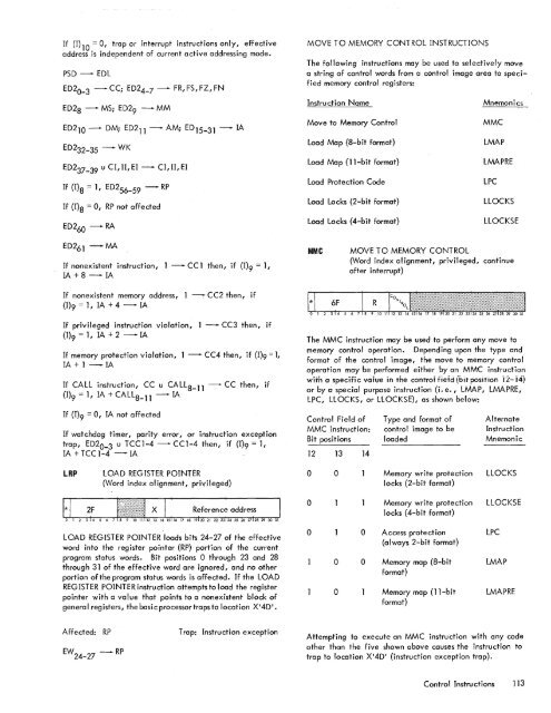
If (I)1O = 0, trap or interrupt instructions only, effectiveaddress is independent of current active addressing mode.PSD -EDLED2 0_ 3-CC; ED24_7 -ED2S - MS; ED29 - MMFR,FS,FZ,FNED210 - DM; ED211 - AM; ED 15 - 31 - IAED232-35 -WKED2 37_ 39u CI, II, EI -If {I)s = 1, ED2 56_ 59-If {I)s = 0, RP not affectedED260 -RACI, II, EIRPMOVE TO MEMORY CONTROL INSTRUCTIONS<strong>The</strong> following instructions may be used to sel ectively movea string of control words from a control image area to specifiedmemory control registers:Instruction NameMove to Memory ControlLoad Map (S-bit format)Load Map ell-bit format)Load Protection CodeLoad Locks (2-bit format)Load Locks (4-bit format)MnemonicsMMCLMAPLMAPRELPCLLOCKSLLOCKSEED261 -MAIf nonexistent instruction, 1 -CCl then, if (1)9 = 1,IA+S-IAMMCMOVE TO MEMORY CONTROL(Word index alignment, privileged, continueafter interrupt)If nonexistent memory address, 1 -(1)9 = 1, IA + 4 - IACC2 then, ifIf privileged instruction violation, 1 -{I)9 = 1, IA + 2 - IACC3 then, ifIf memory protection violation, 1 - CC4 then, if (1)9 = 1,IA + 1 - IAIf CALL instruction, CC u CALLS_ll -(I)9 = 1, IA + CALLS_ll - IACC then, if<strong>The</strong> MMC instruction may be used to perform any move tomemory control operation. Depending upon the type andformat of the control image, the move to memory controloperation may be performed either by an MMC instructionwitn a specifi c vaiue in <strong>The</strong> conTroi fieid (biT position 12-14.)or by a special purpose instruction (i. e., LMAP, LMAPRE,LPC, LLOCKS, or LLOCKSE), as shown below:If (1)9 = 0, IA not affe ctedIf watchdog timer, parity error, or instruction exceptiontrap, ED2 0_3 u TCCl-4 -CCl-4 then, if (1)9= 1,IA + TCC 1-4 - IAControl Field ofMMC instruction:Bit positions12 13 14Type and format ofcontrol image to beloadedAlternateInstructionMnemonicLRPLOA.D REG ISTER POINTER(Word index al ignment, privileged)0 0Memory write protectionlocks (2-bit format)LLOCKSReferenc~ address0Memory write protectionlocks (4-b it format)LLOCKSELOAD REGISTER POINTER loads bits 24-27 of the effectiveword into the register pointer (RP) portion of the currentprogram status words. Bit positions 0 through 23 and 2Sthrough 31 of the effective word are ignored, and no otherportion ofthe program status words is affected. If the LOADREGISTER POINTER instruction attempts to load the registerpointer with a value that points to a nonexistent block ofgeneral registers, the basi c processor traps to location X'4D'.0 00 00Access protection(always 2-bit format)Memory map (S-bitformat)Memory map (ll-bitformat)LPCLMAPLMAPREAffected: RPEW 24_ 27-RPTrap: Instruction exceptionAttempting to execute an MMC instruction with any codeother than the five shown above causes the instruction totrap to location X'4D' (instruction exception trap).Control Instructions 113
- Page 1 and 2:
Xerox 560 ComputerReference Manual9
- Page 5 and 6:
4. INPUT/OUTPUT OPERA TIO NS 142 AG
- Page 7 and 8:
1. XEROX 560 COMPUTER SYSTEMINTRODU
- Page 10 and 11:
Many operations are performed in fl
- Page 12 and 13:
Rapid Context Switching. When respo
- Page 14 and 15:
2. SYSTEM ORGANIZATIONThe elements
- Page 16:
FAST MEMORYARITHMETIC AND CONTROL U
- Page 19 and 20:
INFORMATION BOUNDARIESBasic process
- Page 21 and 22:
(Maximumof eight)Core Core Core Cor
- Page 23 and 24:
3. Diagnostic logic. Each memory dr
- Page 25 and 26:
eference address field of the instr
- Page 27 and 28:
Instruction in memory:Instruction i
- Page 29 and 30:
Real-extended addressing is specifi
- Page 31:
Table 1. Basic Processor Operating
- Page 35 and 36:
DesignationFunctionDesignationFunct
- Page 37 and 38:
InterruptStateDisarmedArmed[$Waitin
- Page 39 and 40:
AddressTable 2. Interrupt Locations
- Page 41 and 42:
is assumed to contain an XPSD or a
- Page 43 and 44:
Table 3. Summary of Trap LocationsL
- Page 45 and 46:
TRAP MASKSThe programmer may mask t
- Page 47 and 48:
PUSH-DOWN STACK LIMIT TRAPPush-down
- Page 49 and 50:
Instruction Name Mnemonic FaultDeci
- Page 51 and 52:
subroutine. However, with certain c
- Page 53 and 54:
3. INSTRUCTION REPERTOIREThis chapt
- Page 55 and 56:
CC1 is unchanged by the instruction
- Page 57 and 58:
Condition code settings:2 3 4 Resul
- Page 59 and 60:
Example 2, odd R field value:Before
- Page 61 and 62:
significance (FS), floating zero (F
- Page 63 and 64:
next sequential register after regi
- Page 65 and 66:
R 1 R2 R3 MeaningoThe effective vir
- Page 67 and 68: Condition code settings:2 3 4 Resul
- Page 69 and 70: MIMULTIPLY IMMEDIATE(Immediate oper
- Page 71 and 72: original contents of register R, re
- Page 73 and 74: Instruction NameCompare HalfwordMne
- Page 75 and 76: Condition code settings:2 3 4 Resul
- Page 77 and 78: 2 3 4 Result of ShiftCircular Shift
- Page 79 and 80: 4. At the completion of the left sh
- Page 81 and 82: Instruction NameFloating Subtract L
- Page 83 and 84: The following table shows the possi
- Page 85 and 86: Table 8.Condition Code Settings for
- Page 87 and 88: PACKED DECIMAL NUMBERSAll decimal a
- Page 89 and 90: DSTDECIMAL STORE(Byte index alignme
- Page 91 and 92: If no indirect addressing or indexi
- Page 93 and 94: Instruction NameMnemonicDesignation
- Page 95 and 96: Both byte strings are C bytes in le
- Page 97 and 98: of the destination byte that caused
- Page 99 and 100: again present, unti I a positive or
- Page 101 and 102: The new contents of register 7 are:
- Page 103 and 104: traps to location X'42 1 as a resul
- Page 105 and 106: If there is sufficient space in the
- Page 107 and 108: If CC1, or CC3, or both CC1 and CC3
- Page 109 and 110: appropriate memory stack locations
- Page 111 and 112: II, EI) are generated by II ORing"
- Page 113 and 114: In the real extended addressing mod
- Page 115 and 116: CAll INSTRUCTIONSEach ofthe four CA
- Page 117: The XPSD instruction' is used for t
- Page 121 and 122: For either memory map format and ei
- Page 123 and 124: initial value plus the initial valu
- Page 125 and 126: Table 9. Status Word 0Field Bits Co
- Page 127 and 128: READ INTERRUPT INHIBITSThe followin
- Page 129 and 130: Table 11.Read Direct Mode 9 Status
- Page 131 and 132: SET ALARM INDICATORThe following co
- Page 133 and 134: INPUT jOUTPUT INSTRUCTIONSThe I/o i
- Page 135 and 136: Table 13.Description of I/o Instruc
- Page 137 and 138: Table 15.Device Status Byte (Regist
- Page 139 and 140: Table 16. Operational Status Byte (
- Page 141 and 142: Table 19.Status Response Bits for A
- Page 143 and 144: If CC4 = 0, the MIOP is in a normal
- Page 145 and 146: 2 3 4 Meaningo 0 I/o address not re
- Page 147 and 148: The functions of bits within the DC
- Page 149 and 150: 4. Each unit-record controller (int
- Page 151 and 152: Interrupt at Channel End (Bit Posit
- Page 153 and 154: Transfer in Channel. A control lOCO
- Page 155 and 156: Otherwise, the first word of the ne
- Page 157 and 158: Depending upon the characteristics
- Page 159 and 160: change the rate on the primary cons
- Page 161 and 162: Location(hex) (dec)20 3221 3322 342
- Page 163 and 164: Table 22.Diagnostic Control (P-Mode
- Page 165 and 166: at its normal rate (e. g., fixed du
- Page 167 and 168: SET LOW CLOCK MARGINSThis command c
- Page 169 and 170:
BP STATUS AND NO.Th i s group of i
- Page 171 and 172:
Input5MPri ntout5MFunctionStore X 1
- Page 173 and 174:
6. SYSTEM CONFIGURATION CONTROLPool
- Page 175 and 176:
Table 25. Functions of Processor Cl
- Page 177:
Table 26. Functions of Memory Unit
- Page 180 and 181:
STANDARD 8-BIT COMPUTER CODES (EBCD
- Page 182 and 183:
STANDARD SYMBOL-CODE CORRESPONDENCE
- Page 184 and 185:
STANDARD SYMBOL-CODE CORRESPONDENCE
- Page 186 and 187:
TABLE OF POWERS OF SIXTEEN II162564
- Page 188 and 189:
HEXADECIMAL-DECIMAL INTEGER CONVERS
- Page 190 and 191:
HEXADECIMAL-DECIMAL INTEGER CONVERS
- Page 192 and 193:
HEXADECIMAL-DECIMAL INTEGER CONVERS
- Page 194 and 195:
HEXADECIMAL-DECIMAL FRACTION CONVER
- Page 196 and 197:
HEXADECIMAL-DECIMAL FRACTION CONVER
- Page 198 and 199:
APPENDIX B.GLOSSARY OF SYMBOLIC TER
- Page 200 and 201:
TermMeaningTermMeaningWKxWrite key
- Page 202 and 203:
Table C-2. Memory Unit Status Regis
- Page 204 and 205:
Y OYf'lV r'f'lrnf'lrtil"\n'''' ....
- Page 206:
701 South Aviation BoulevardEI Segu