to as conversion values. <strong>The</strong> intermediate results of theseinstructions are accumulated in internal basic processorregisters unti I the instruction is completed; the result isthen loaded into the appropriate general register. Bothinstructions use a counter (n) that is set to 0 at the beginningof the instruction execution and is incremented by 1 witheach iteration, until a total of 32 iterations has beenperformed.If a memory parity or protection violation trap occurs duringthe execution of either instruction, the instruction sequenceis aborted (without having changed the contents ofregister R or Rul) and may be restarted (at the beginning ofthe instruction sequence) after the trap routine is processed.eVACONVERT BY ADDITION(yVord index alignment)CONVERT BY ADDITION initially clears the internal A registerand sets an internal counter (n) to O. If bit position nof register Rul contains a 1, CVA adds the nth conversionvalue (contents of the word location pointed to by the effectiveaddress plus n) to the contents of the A register,accumulates the sum in the A register, and increments nby <strong>1.</strong> If bit position n of register Ru 1 contains a 0, CVAonly increments n. If n is less than 32 after being incremented,the next bit position of register Rul is examined,and the addition process continues through n equal to 31;the resu It is then loaded into register R. If, on any iteration,the sum has exceeded the value 2 32 - 1, CCl is setto 1 i otherwise, CCl is reset to O.Affected: (R), CC1, CC3, CC4O-A,O-nIf (Rul) =1, then (EWL + n) + (A) -A, n + 1 -nIf (Run =0. then n + 1-n, 'n 'If n < 32, repeat; otherwise, (A) -next instruction.Condition code settings:2 3 4 Resu It in R- 0 0 Zero.- 0 Bit 0 of register R is a <strong>1.</strong>nR and continue toOBit 0 of register R is a 0 and bit positions 1-31of register R contain at least one <strong>1.</strong>evsCONVERT BY SUBTRACTION(yVord index alignment)CONVERT BY SUBTRACTION loads the internal A registerwith the contents of register R, clears the internal B register,and sets an internal counter (n) to O. All conversionvalues are considered to be 32-bit positive quantities. Ifthe nth conversion value (the contents of the word locationpointed to by the effective address plus n) is equal to orless than the current contents of the A register, CVS incrementsn by 1, adds the two's complement of the nth conversionvalue to the contents of the A register, stores thesum in the A regi ster, and stores ali n bi t position n of theB register. If the nth conversion value is greater than thecurrent contents of the A register, CVS only increments nby <strong>1.</strong> If n is less than 32 after being incremented, thenext conversion value is compared and the process continuesthrough n equal to 31; the remainder in the A registeris loaded into register R, and the converted quantityin the B register is loaded into register Ru<strong>1.</strong>Affected: (R), (Rul), CC3, CC4(R)-A, O-B, O-nIf (EWL + n) $ (A) then A - (EWL + n) -A,l-B ,n + l-nnIf (EWL + n) > (A) then n + 1-nIf n < 32, repeat; otherwise, (A) - R, (B) - Ru1 andcontinue to the next instruction.Condition code settings:2 3 4 Result in Rul- 0 0 Zero.oBit 0 of register Ru i is a Lo BitOofregisterRu1 is a 0 and bit positions1-31 of register Ru 1 contain at leastone <strong>1.</strong>FLOATING-POINT ARITHMETIC INSTRUCTIONS<strong>The</strong> floating-point arithmetic instructions are:Instruction f'~amcFloating Add Short~,~ncmon;cFASo- - Sum is correct (less than ~2).Floating Add LongFAL- - Sum is greater than 2 32 _<strong>1.</strong>Floating Subtract ShortFSS74 Floating-Point Arithmetic Instructions
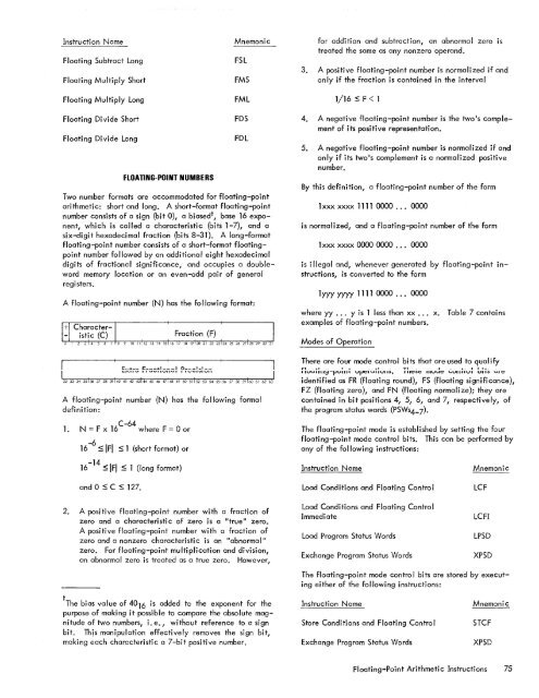
Instruction NameFloating Subtract LongFloating Multiply ShortFloating Multiply LongMnemonicFSLFMSFMLfor addition and subtraction, an abnormal zero istreated the same as any nonzero operand.3. A positive floating-point number is normalized if andonly if the fraction is contained in the interval1/16 $ F < 1Floating Divide ShortFloating Divide LongFLOATING-POINT NUMBERSFDSFDLTwo number formats are accommodated for floating-pointarithmetic: short and long. A short-format floating-pointnumber consists of a sign (bit 0), a biased t , base 16 exponent,which is called a characteristic (bits 1-7), and asix-digit hexadecimal fraction (bits 8-31). A long-formatfloating-point number consists of a short-format floatingpointnumber followed by an additional eight hexadecimaldigits of fractional significance, and occupies a doublewordmemory location or an even-odd pair of generalregisters.A floating-point number (N) has the following format:4. A negative floating-point number is the two1s complementof its positive representation.5. A negative floating-point number is normalized if andonly if its two1s complement is a normalized positivenumber.By this definition, a floating-point number of the form1 xxx xxxx 1111 0000 . .• 0000is normalized, and a floating-point number of the form1 xxx xxxx 0000 0000 . .. 0000is illegal and, whenever generated by floating-point instructions,is converted to the form1 yyy yyyy 1111 0000 . .. 0000where yy ... Y is 1 less than xx ... x.examples of floating-point numbers.Table 7 containsModes of OperationA floating-point number (N) has the following formaldefinition:<strong>1.</strong>C-64N = F x 16where F = 0 or-616 s IFI s 1 (short format) or-1416 S IFI $ 1 {long format)<strong>The</strong>re are four mode control bits that are used to qual ify£"1 __ . .L- __ .• .L ____ .I..- _ _ TI _ _ ___ I. __ L.. I I -.<strong>1.</strong>__ _IIUUIIII~-PUIIII Upt::IUIIUII:>. 1111::::>1::: IIIUUI::: ,",UIIIIUI Uti:> utI:::identified as FR (floating round), FS (floating significance),FZ (floating zero), and FN (floating normalize); they arecontained in bit positions 4, 5, 6, and 7, respectively, ofthe program status words (PSWs4_7).<strong>The</strong> floating-point mode is established by setting the fourfloating-point mode control bits. This can be performed byany of the following instructions:Instruction NameMnemonicand 0 $ C $ 127.Load Conditions and Floating ControlLCF2. A positive floating-point number with a fraction ofzero and a characteristic of zero is a "true" zero.A positive floating-point number with a fraction ofzero and a nonzero characteristic is an "abnorma I"zero. For floating-point multiplication and division,an abnormal zero is treated as a true zero. However,Load Conditions and Floating ControlImmediateLoad Program Status WordsExchange Program Status WordsLCFILPSDXPSD<strong>The</strong> floating-point mode control bits are stored by executingeither of the following instructions:t <strong>The</strong> bias value of 4016 is added to the exponent for thepurpose of making it possible to compare the absolute magnitudeof two numbers, i. e., without reference to a signbit. This manipulation effectively removes the sign bit,making each characteristic a 7-bit positive number.Instruction NameStore Conditions and Floating ControlExchange Program Status WordsMnemonicSTCFXPSDFloating-Point Arithmetic Instructions 75
- Page 1 and 2:
Xerox 560 ComputerReference Manual9
- Page 5 and 6:
4. INPUT/OUTPUT OPERA TIO NS 142 AG
- Page 7 and 8:
1. XEROX 560 COMPUTER SYSTEMINTRODU
- Page 10 and 11:
Many operations are performed in fl
- Page 12 and 13:
Rapid Context Switching. When respo
- Page 14 and 15:
2. SYSTEM ORGANIZATIONThe elements
- Page 16:
FAST MEMORYARITHMETIC AND CONTROL U
- Page 19 and 20:
INFORMATION BOUNDARIESBasic process
- Page 21 and 22:
(Maximumof eight)Core Core Core Cor
- Page 23 and 24:
3. Diagnostic logic. Each memory dr
- Page 25 and 26:
eference address field of the instr
- Page 27 and 28:
Instruction in memory:Instruction i
- Page 29 and 30: Real-extended addressing is specifi
- Page 31: Table 1. Basic Processor Operating
- Page 35 and 36: DesignationFunctionDesignationFunct
- Page 37 and 38: InterruptStateDisarmedArmed[$Waitin
- Page 39 and 40: AddressTable 2. Interrupt Locations
- Page 41 and 42: is assumed to contain an XPSD or a
- Page 43 and 44: Table 3. Summary of Trap LocationsL
- Page 45 and 46: TRAP MASKSThe programmer may mask t
- Page 47 and 48: PUSH-DOWN STACK LIMIT TRAPPush-down
- Page 49 and 50: Instruction Name Mnemonic FaultDeci
- Page 51 and 52: subroutine. However, with certain c
- Page 53 and 54: 3. INSTRUCTION REPERTOIREThis chapt
- Page 55 and 56: CC1 is unchanged by the instruction
- Page 57 and 58: Condition code settings:2 3 4 Resul
- Page 59 and 60: Example 2, odd R field value:Before
- Page 61 and 62: significance (FS), floating zero (F
- Page 63 and 64: next sequential register after regi
- Page 65 and 66: R 1 R2 R3 MeaningoThe effective vir
- Page 67 and 68: Condition code settings:2 3 4 Resul
- Page 69 and 70: MIMULTIPLY IMMEDIATE(Immediate oper
- Page 71 and 72: original contents of register R, re
- Page 73 and 74: Instruction NameCompare HalfwordMne
- Page 75 and 76: Condition code settings:2 3 4 Resul
- Page 77 and 78: 2 3 4 Result of ShiftCircular Shift
- Page 79: 4. At the completion of the left sh
- Page 83 and 84: The following table shows the possi
- Page 85 and 86: Table 8.Condition Code Settings for
- Page 87 and 88: PACKED DECIMAL NUMBERSAll decimal a
- Page 89 and 90: DSTDECIMAL STORE(Byte index alignme
- Page 91 and 92: If no indirect addressing or indexi
- Page 93 and 94: Instruction NameMnemonicDesignation
- Page 95 and 96: Both byte strings are C bytes in le
- Page 97 and 98: of the destination byte that caused
- Page 99 and 100: again present, unti I a positive or
- Page 101 and 102: The new contents of register 7 are:
- Page 103 and 104: traps to location X'42 1 as a resul
- Page 105 and 106: If there is sufficient space in the
- Page 107 and 108: If CC1, or CC3, or both CC1 and CC3
- Page 109 and 110: appropriate memory stack locations
- Page 111 and 112: II, EI) are generated by II ORing"
- Page 113 and 114: In the real extended addressing mod
- Page 115 and 116: CAll INSTRUCTIONSEach ofthe four CA
- Page 117 and 118: The XPSD instruction' is used for t
- Page 119 and 120: If (I)1O = 0, trap or interrupt ins
- Page 121 and 122: For either memory map format and ei
- Page 123 and 124: initial value plus the initial valu
- Page 125 and 126: Table 9. Status Word 0Field Bits Co
- Page 127 and 128: READ INTERRUPT INHIBITSThe followin
- Page 129 and 130: Table 11.Read Direct Mode 9 Status
- Page 131 and 132:
SET ALARM INDICATORThe following co
- Page 133 and 134:
INPUT jOUTPUT INSTRUCTIONSThe I/o i
- Page 135 and 136:
Table 13.Description of I/o Instruc
- Page 137 and 138:
Table 15.Device Status Byte (Regist
- Page 139 and 140:
Table 16. Operational Status Byte (
- Page 141 and 142:
Table 19.Status Response Bits for A
- Page 143 and 144:
If CC4 = 0, the MIOP is in a normal
- Page 145 and 146:
2 3 4 Meaningo 0 I/o address not re
- Page 147 and 148:
The functions of bits within the DC
- Page 149 and 150:
4. Each unit-record controller (int
- Page 151 and 152:
Interrupt at Channel End (Bit Posit
- Page 153 and 154:
Transfer in Channel. A control lOCO
- Page 155 and 156:
Otherwise, the first word of the ne
- Page 157 and 158:
Depending upon the characteristics
- Page 159 and 160:
change the rate on the primary cons
- Page 161 and 162:
Location(hex) (dec)20 3221 3322 342
- Page 163 and 164:
Table 22.Diagnostic Control (P-Mode
- Page 165 and 166:
at its normal rate (e. g., fixed du
- Page 167 and 168:
SET LOW CLOCK MARGINSThis command c
- Page 169 and 170:
BP STATUS AND NO.Th i s group of i
- Page 171 and 172:
Input5MPri ntout5MFunctionStore X 1
- Page 173 and 174:
6. SYSTEM CONFIGURATION CONTROLPool
- Page 175 and 176:
Table 25. Functions of Processor Cl
- Page 177:
Table 26. Functions of Memory Unit
- Page 180 and 181:
STANDARD 8-BIT COMPUTER CODES (EBCD
- Page 182 and 183:
STANDARD SYMBOL-CODE CORRESPONDENCE
- Page 184 and 185:
STANDARD SYMBOL-CODE CORRESPONDENCE
- Page 186 and 187:
TABLE OF POWERS OF SIXTEEN II162564
- Page 188 and 189:
HEXADECIMAL-DECIMAL INTEGER CONVERS
- Page 190 and 191:
HEXADECIMAL-DECIMAL INTEGER CONVERS
- Page 192 and 193:
HEXADECIMAL-DECIMAL INTEGER CONVERS
- Page 194 and 195:
HEXADECIMAL-DECIMAL FRACTION CONVER
- Page 196 and 197:
HEXADECIMAL-DECIMAL FRACTION CONVER
- Page 198 and 199:
APPENDIX B.GLOSSARY OF SYMBOLIC TER
- Page 200 and 201:
TermMeaningTermMeaningWKxWrite key
- Page 202 and 203:
Table C-2. Memory Unit Status Regis
- Page 204 and 205:
Y OYf'lV r'f'lrnf'lrtil"\n'''' ....
- Page 206:
701 South Aviation BoulevardEI Segu