Depending upon the type of addressing, the referenceaddress of the PSS instruction is converted into an effectivevirtual doubleword address, as described under "PSS AddressCalculations", in Chapter 2. Except for the Register BlockPointer field (bit positions 56-59) and the interrupt groupinhibit bits (bit positions 37, 38, and 39), the contents ofthe effective location are always loaded as the new PSWs.If the lP flag (bit 8 of the PSS instruction) is a 1, theRegister Block Pointer of the new PSWs is also loaded. Ifthe lP flag is a 0, the old Register Block Pointerisretained.<strong>The</strong> interrupt group inhibit bits of the new PSWs are 1I0Red llwith the corresponding bits of the old PSWs.<strong>The</strong> current environment (comprised of 20 words) is storedin memory stack locations having the following relativeaddresses: initial TSA+1 through initial TSA+16, initialTSA+25, and initial TSA+26. Memory stack locationshaving ref-ative addresses of initial TSA+17 through initialTSA+24, initial TSA+27, and initial TSA+28 are reservedand the contents are indeterminate.Memory Stack:(General Register n) - (initial TSA+(n+l) where n hasascending values from 0 through 15.PSW1 -PSW2 -(initial TSA+25)(initial TSA+26)Status Stack Pointer Doubleword:TSA+1 - TSA unti I terminal TSA=initial TSA+28iWord Count + 1 - Word Count unti I terminal WordCount = initial Word Count + 28, (if Word Count>32,767, set bit 48 to 1);Space Count - 1 - Space Count unti I terminal SpaceCount = initial Space Count - 28 (if Space Count = 0,Space Count - 1 is indeterminate).<strong>The</strong> parameters of the Status Stack Pointer Doubleword (ascontained within working registers) are appropriately modifiedto reflect the progress of the PSS instruction andconditions of the memory stack (i. e., the TSA and WordCount are incremented and the Space Count is decrementedfor each memory word location accessed, as described underStatus Stack Pointer Doubleword).If the Word Count exceeds 32,767 (maximum count forbits 49-63) or if the Space Count is reduced to zero beforethe PSS instruction is completed, the stacking operationscontinue unti I 28 words have been pushed (i. e., no trappingoccurs). When the Word Count exceeds 32,767, bit 48 isset to a <strong>1.</strong> Attempting to decrement the Space Count belowzero causes the Space Count to become indeterminate.Affected: (PSWs), CC, Memory Stack, Status Stack PointerDoubleword.(PSWs) and CC:EDO_3-CC;ED4-7- FR, FS, FZ, FN;ED8-MS;ED9-MM;ED10-DMiED11-AMiED15-31 -IAiED32-35-WK;ED37-39 u CI, II, EI - CI, II, EI(Note: "u ll represents inclusive OR. )ED 56 - 59 - RP on Iy if (I8) = 1ED60- RAED61-MAPLSPULL STATUS (nonaddressing, privileged)PULL STATUS, in conjunction with the Status Stack PointerDoubleword, may cause one or more of the following functionsto be performed:<strong>1.</strong> Selectively load a new environment (PSWs and 16 generalregisters) from the memory stack; or,2. Selectively load default PSWs from dedicated memorylocations; and,3. Selectively clear and arm or clear and disarm thehighest priority level currently in the active state.If the initial Word Count of Status Stack Pointer Doublewordis equal to or greater than 28, a new environment isloaded from the memory stack. Twenty eight memory stacklocations are accessed in a descending sequence, startingat a location having an address equal to the initial TSA(part of the Status Stack Pointer Doubleword).<strong>The</strong> hardwareselects and loads the contents of 20 memory locationsinto the general registers and as the PSWs (i. e., the contentsof locations having relative addresses of initial TSA-2,initial TSA-3, and initial TSA-12 through initial TSA-27).<strong>The</strong> contents of 10 memory stack locations (having relativeaddresses equal to initial TSA, initial TSA-l, and initialTSA-4 through initial TSA-11) are ignored.Portions of the new PSWs are dependent upon the LP flagII-Ln\ r~t nlr- I.- 1<strong>1.</strong><strong>1.</strong>..\011 OJ or me fL.) JnsrruclJon as well as me mTerrupT groupinhibit bits of the old PSWs and the PSWs as pulled fromthe memory stack. If the LP flag is a 1, a new RegisterBlock Pointer (as pulled from the memory stack) is loadedas part of the new PSWs. If the LP flag is a 0, the old RegisterBlock Pointer is retained as the Register Block Pointerfor the new PSWs. <strong>The</strong> new interrupt group inhibit bits (CI,104 Push-Down Instructions (Privileged)
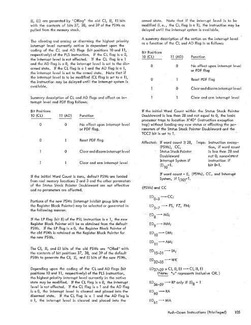
II, EI) are generated by II ORing" the old CI, II, EI bitswith the contents of bits 37, 38, and 39 of the PSWs aspu II ed from the memory stack.<strong>The</strong> clearing and arming or disarming the highest priorityinterrupt level currently active is dependent upon thecoding of the CL and AD flags (bit positions 10 and 11,respectively) of the PLS instruction. If the CL flag is a 0 7the interrupt level is not affected. If the CL flag fs-a 1and the AD flag is a Or the interrupt level is set to the disarmedstate. If the CL flag is a 1 and the AD flag is a 1rthe interrupt level is set to the armed state. Note that -ifthe interrupt level is to be modifie~ (CL flag is set to a 1),the instruction maybe delayed unti I the interrupt <strong>system</strong> isavai lable. -Summary description of CL and AD flags and effect on in-terrupt level and PDF flag follows:armed state. Note that if the interrupt_level is to bemodified (i. e., the CL flag is a 1), the instruction may bedelayed unti I the interrupt <strong>system</strong> is avai lab Ie.A summary description of the action on the interrupt leveias a function of the C1 and AD .flag is as follows:Bit Positions10 (CL)oo11 (AD)ooFunctionNo effect upon interrupt levelor PDF flagReset PDF flagClear and disarm interrupt levelClear and arm interrupt levelBit Positions10 (CL)oo11 (AD)ooFunctionNo effect upon interrupt levelor PDF flag.Reset PDF flagClear and disClrm interrupt levelClear and arm interrupt levelIf the initial Word Count within the Status Stack PointerDoubleword is less than 28 cmd not equal to 0, the basicprocessor traps to location X'4D~ (instruction exceptiontrap) without loading-any new status or affecting the parametersof the Status Stack Pointer Doubleword and ther-CC2 bit is set to <strong>1.</strong>Affected: If word count ~ 28,(PSWs), CC,Status Stack PointerDoublewordInterrupt System if(1)10=<strong>1.</strong>Traps: Instruction exception,if word countis less than 28 andnot 0; nonexistentinstruction ifbit 0=<strong>1.</strong>If the initial Word Count is zero r default PSWs are loaded -from real memory locations 2 and 3 and the other parametersof the Status Stack Pointer Doubleword are not effectiveand no parameters are affected.Portions of the new PSWs (interrupt inhibit group bits andthe Register Block Pointer) may be selected or generated inthe following manner:If the LP flag (bit 8) of the PSL instruction is a 1r the newRegister Block Pointer wi II be as obtained from the defaultPSWs. If the LP flag is a 0, the Register Block Pointer ofthe old PSWs is retained as the Register Block Pointer forthe new PSWs.<strong>The</strong> CI, II, and EI bits of the old PSWs are "ORed II withthe contents of bit positions 37, 38 r and 39 of the defaultPSWs to generate the CI, II, and EI bits of the new PSWs.Depending upon the coding of the CL and AD flags (bitpositions 10 and 11, respectively) of the PLS instruction,the highest priority interrupt level currently in the activestate may be modified. If the CL flag is a 0, the interruptlevel is not affected. If the CL flag is a 1 and the AD flagis a 0, the interrupt level is cleared and placed into thedisarmed state. If the CL flag is a 1 and the AD flag isa 1, the interrupt level is cleared and placed into the(PSWs) and CCIf word count = 0, (PSWs), ec, and InferruptSystem, if 1(10)=<strong>1.</strong>ED O_ 3-CC;ED 5-7 -ED 8-MS;-ED 9-MM;ED lO-DM;ED 11-AM;ED 15- 31-FS, FZ, FN;IA;ED 32_ 35-WKED37-39 u CI, II,-EI -CI, II, EI(Note: "u" represents inclusive OR. )[D 56- 59- RP only if (1)8= 1ED 60-RAED 61-MApush-Down Instructions (Privi leged) 105
- Page 1 and 2:
Xerox 560 ComputerReference Manual9
- Page 5 and 6:
4. INPUT/OUTPUT OPERA TIO NS 142 AG
- Page 7 and 8:
1. XEROX 560 COMPUTER SYSTEMINTRODU
- Page 10 and 11:
Many operations are performed in fl
- Page 12 and 13:
Rapid Context Switching. When respo
- Page 14 and 15:
2. SYSTEM ORGANIZATIONThe elements
- Page 16:
FAST MEMORYARITHMETIC AND CONTROL U
- Page 19 and 20:
INFORMATION BOUNDARIESBasic process
- Page 21 and 22:
(Maximumof eight)Core Core Core Cor
- Page 23 and 24:
3. Diagnostic logic. Each memory dr
- Page 25 and 26:
eference address field of the instr
- Page 27 and 28:
Instruction in memory:Instruction i
- Page 29 and 30:
Real-extended addressing is specifi
- Page 31:
Table 1. Basic Processor Operating
- Page 35 and 36:
DesignationFunctionDesignationFunct
- Page 37 and 38:
InterruptStateDisarmedArmed[$Waitin
- Page 39 and 40:
AddressTable 2. Interrupt Locations
- Page 41 and 42:
is assumed to contain an XPSD or a
- Page 43 and 44:
Table 3. Summary of Trap LocationsL
- Page 45 and 46:
TRAP MASKSThe programmer may mask t
- Page 47 and 48:
PUSH-DOWN STACK LIMIT TRAPPush-down
- Page 49 and 50:
Instruction Name Mnemonic FaultDeci
- Page 51 and 52:
subroutine. However, with certain c
- Page 53 and 54:
3. INSTRUCTION REPERTOIREThis chapt
- Page 55 and 56:
CC1 is unchanged by the instruction
- Page 57 and 58:
Condition code settings:2 3 4 Resul
- Page 59 and 60: Example 2, odd R field value:Before
- Page 61 and 62: significance (FS), floating zero (F
- Page 63 and 64: next sequential register after regi
- Page 65 and 66: R 1 R2 R3 MeaningoThe effective vir
- Page 67 and 68: Condition code settings:2 3 4 Resul
- Page 69 and 70: MIMULTIPLY IMMEDIATE(Immediate oper
- Page 71 and 72: original contents of register R, re
- Page 73 and 74: Instruction NameCompare HalfwordMne
- Page 75 and 76: Condition code settings:2 3 4 Resul
- Page 77 and 78: 2 3 4 Result of ShiftCircular Shift
- Page 79 and 80: 4. At the completion of the left sh
- Page 81 and 82: Instruction NameFloating Subtract L
- Page 83 and 84: The following table shows the possi
- Page 85 and 86: Table 8.Condition Code Settings for
- Page 87 and 88: PACKED DECIMAL NUMBERSAll decimal a
- Page 89 and 90: DSTDECIMAL STORE(Byte index alignme
- Page 91 and 92: If no indirect addressing or indexi
- Page 93 and 94: Instruction NameMnemonicDesignation
- Page 95 and 96: Both byte strings are C bytes in le
- Page 97 and 98: of the destination byte that caused
- Page 99 and 100: again present, unti I a positive or
- Page 101 and 102: The new contents of register 7 are:
- Page 103 and 104: traps to location X'42 1 as a resul
- Page 105 and 106: If there is sufficient space in the
- Page 107 and 108: If CC1, or CC3, or both CC1 and CC3
- Page 109: appropriate memory stack locations
- Page 113 and 114: In the real extended addressing mod
- Page 115 and 116: CAll INSTRUCTIONSEach ofthe four CA
- Page 117 and 118: The XPSD instruction' is used for t
- Page 119 and 120: If (I)1O = 0, trap or interrupt ins
- Page 121 and 122: For either memory map format and ei
- Page 123 and 124: initial value plus the initial valu
- Page 125 and 126: Table 9. Status Word 0Field Bits Co
- Page 127 and 128: READ INTERRUPT INHIBITSThe followin
- Page 129 and 130: Table 11.Read Direct Mode 9 Status
- Page 131 and 132: SET ALARM INDICATORThe following co
- Page 133 and 134: INPUT jOUTPUT INSTRUCTIONSThe I/o i
- Page 135 and 136: Table 13.Description of I/o Instruc
- Page 137 and 138: Table 15.Device Status Byte (Regist
- Page 139 and 140: Table 16. Operational Status Byte (
- Page 141 and 142: Table 19.Status Response Bits for A
- Page 143 and 144: If CC4 = 0, the MIOP is in a normal
- Page 145 and 146: 2 3 4 Meaningo 0 I/o address not re
- Page 147 and 148: The functions of bits within the DC
- Page 149 and 150: 4. Each unit-record controller (int
- Page 151 and 152: Interrupt at Channel End (Bit Posit
- Page 153 and 154: Transfer in Channel. A control lOCO
- Page 155 and 156: Otherwise, the first word of the ne
- Page 157 and 158: Depending upon the characteristics
- Page 159 and 160: change the rate on the primary cons
- Page 161 and 162:
Location(hex) (dec)20 3221 3322 342
- Page 163 and 164:
Table 22.Diagnostic Control (P-Mode
- Page 165 and 166:
at its normal rate (e. g., fixed du
- Page 167 and 168:
SET LOW CLOCK MARGINSThis command c
- Page 169 and 170:
BP STATUS AND NO.Th i s group of i
- Page 171 and 172:
Input5MPri ntout5MFunctionStore X 1
- Page 173 and 174:
6. SYSTEM CONFIGURATION CONTROLPool
- Page 175 and 176:
Table 25. Functions of Processor Cl
- Page 177:
Table 26. Functions of Memory Unit
- Page 180 and 181:
STANDARD 8-BIT COMPUTER CODES (EBCD
- Page 182 and 183:
STANDARD SYMBOL-CODE CORRESPONDENCE
- Page 184 and 185:
STANDARD SYMBOL-CODE CORRESPONDENCE
- Page 186 and 187:
TABLE OF POWERS OF SIXTEEN II162564
- Page 188 and 189:
HEXADECIMAL-DECIMAL INTEGER CONVERS
- Page 190 and 191:
HEXADECIMAL-DECIMAL INTEGER CONVERS
- Page 192 and 193:
HEXADECIMAL-DECIMAL INTEGER CONVERS
- Page 194 and 195:
HEXADECIMAL-DECIMAL FRACTION CONVER
- Page 196 and 197:
HEXADECIMAL-DECIMAL FRACTION CONVER
- Page 198 and 199:
APPENDIX B.GLOSSARY OF SYMBOLIC TER
- Page 200 and 201:
TermMeaningTermMeaningWKxWrite key
- Page 202 and 203:
Table C-2. Memory Unit Status Regis
- Page 204 and 205:
Y OYf'lV r'f'lrnf'lrtil"\n'''' ....
- Page 206:
701 South Aviation BoulevardEI Segu