

1. xerox 560 computer system - The UK Mirror Service
1. xerox 560 computer system - The UK Mirror Service
1. xerox 560 computer system - The UK Mirror Service

Create successful ePaper yourself
Turn your PDF publications into a flip-book with our unique Google optimized e-Paper software.
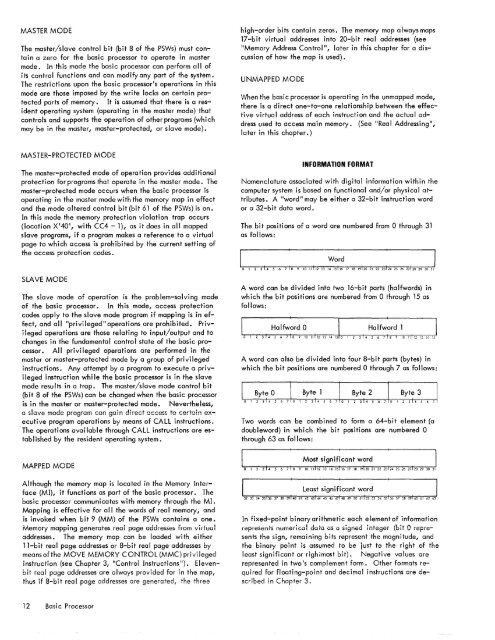
MASTER MODE<strong>The</strong> master/slave control bit (bit 8 of the PSWs) must containa zero for the basic processor to operate in mastermode. In th is mode the basic processor can perform a II ofits control functions and can modify any part of the <strong>system</strong>.<strong>The</strong> restrictions upon the basic processor1s operations in thismode are those imposed by the write locks on certain protectedparts of memory. It is assumed that there is a residentoperating <strong>system</strong> (operating in the master mode) thatcontrols and supports the operation of other programs (whichmay be in the master, master-protected, or slave mode).high-order bits contain zeros. <strong>The</strong> memory map always maps17-bit virtual addresses into 20-bit real addresses (seeIIMemory Address Control II, later in this chapter for a discussionof how the map is used).UNMAPPED MODEWhen the basic processor is operating in the unmapped mode,there is a direct one-to-one relationship between the effectivevirtual address of each instruction and the actual addressused to access main memory. (See II Rea I Addressing ll ,later in this chapter.)MASTER-PROTECTED MODE<strong>The</strong> master-protected mode of operation provides additionalprotection for programs that operate in the master mode. <strong>The</strong>master-protected mode occurs when the basic processor isoperating in the master mode with the memory map in effectand the mode altered control bit (bit 61 of the PSWs) is on.In this mode the memory protection violation trap occurs(location X I 40 I , with CC4 = 1), as it does in all mappedslave programs, if a program makes a reference to a virtualpage to which access is prohibited by the current setting ofthe access protecti on codes.INFORMATION FORMATNomenclature associated with digital information within the<strong>computer</strong> <strong>system</strong> is based on functional and/or physical attributes.A "word" may be either a 32-bit instruction wordor a 32-bit data word.<strong>The</strong> bit positions of a word are numbered from 0 through 31as follows:SLAVE MODE<strong>The</strong> slave mode of operation is the problem-solving modeof the basic processor. In this mode, access protectioncodes apply to the slave mode program if mapping is in effect,and all IIprivileged II operations are prohibited. Privilegedoperations are those relating to input/output and tochanges in the fundamental control state of the basic processor.All privileged operations are performed in themaster or master-protected mode by a group of privilegedinstructions. Any attempt by a program to execute a privilegedinstruction whi Ie the basic processor is in the slavemode results in a trap. <strong>The</strong> master/slave mode control bit(bit 8 of the PSWs) can be changed when the basic processoris in the master or master-protected mode. Nevertheless,a s!aVe mode program can gain direct access to certai!1 executiveprogram operations by means of CALL instructions.-<strong>The</strong> operations avai lable through CALL instructions are establishedby the resident operating <strong>system</strong>.A word can be divided into two 16-bit parts (halfwords) inwh ich the bit positions are numbered from 0 through 15 asfollows:A word can also be divided into four 8-bit parts (bytes) inwhich the bit positions are numbered 0 through 7 as follows:Two words can be combined to form a 64-bit element (adoubleword) in which the bit positions are numbered 0through 63 as follows:MAPPED MODEAlthough the memory map is located in the Memory Interface(MI), it functions as part of the basic processor. <strong>The</strong>basic processor communicates with memory through the MI.Mapping is effective for all the words of real memory, andis invoked when bit 9 (MM) of the PSWs contains a one.Memory mapping generates real page addresse:s from vir-tualaddresses. <strong>The</strong> memory map can be loaded with either11-bit real page addresses or 8-bit real page addresses bymeansofthe MOVE MEMORY CONTROL (MMC) privilegedinstruction (see Chapter 3, "Control Instructions "). Elevenbitreal page addresses are always provided for in the map,thus if 8-bit real page addresses are generated, the threeI : Least Signif~cant word: In " " "I~ ~ '" '" ~ " " ,,1« " " ,,:« " '" "I" ,; ,. ,,' ~ " " "1M,, " "In fixed-point binary arithmetic each element of informationrepresents nurneiical data as a signed integer (bit 0 representsthe sign, remaining bits represent the magnitude, andthe binary point is assumed to be just to the right of theleast significant or righi-most bit). Negative va lues arerepresented in two1s complement form. Other formats requiredfor floating-point and decimal instructions are describedin Chapter 3.12 Basic Processor


