

1. xerox 560 computer system - The UK Mirror Service
1. xerox 560 computer system - The UK Mirror Service
1. xerox 560 computer system - The UK Mirror Service

You also want an ePaper? Increase the reach of your titles
YUMPU automatically turns print PDFs into web optimized ePapers that Google loves.
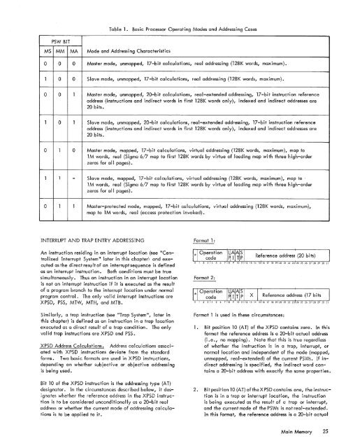
Table <strong>1.</strong> Basic Processor Operating Modes and Addressing CasesPSW BITMS MM MA Mode and Addressing Characteristics0 0 0 Master mode, unmapped, 17-bit calculations, real addressing (128K words, maximum).1 0 0 Slave mode, unmapped, 17-bit calculations, real addressing (128K words, maximum).0 0 1 Master mode, unmapped, 20-bit calculations, real-extended addressing, 17-bit instruction referenceaddress (instructions and indirect words in first 128K words only), indexed and indirect addresses are20 bits.1 0 1 Slave mode, unmapped, 20-bit calculations, real-extended addressing, 17-bit instruction referenceaddress (instructions and indirect words in first 128K words only), indexed and indirect addresses are20 bits.0 1 0 Master mode, mapped, 17-bit calculations, virtual addressing (128K words, maximum), map to1M words, real (Sigma 6/7 map to first 128K words by virtue of loading map with three high-orderzeros for all pages).1 1 - Slave mode, mapped, 17-bit calculations, virtual addressing (128K words, maximum), map to1M words, real (Sigma 6/7 map to first 128K words by virtue of loading map with three high-orderzeros for a II pages).0 1 1 Master-protected mode, mapped, 17-bit calculations, virtual addressing (128K words, maximum),map to 1 M words, rea I (access protection invoked).INTERRUPT AND TRAP ENTRY ADDRESSINGAn instruction residing in an interrupt location (see "CentralizedInterrupt System" later in this chapter! and executedasthe directresultof an interruptsequence is definedas an interrupt instruction. Both conditions must be truesimultaneously. Thus an instruction in an interrupt locationis not an interrupt instruction if it is executed as the resultof a program branch to the interrupt location under normalprogram control. <strong>The</strong> only va I id interrupt instructions areXPSD, PSS, MTW, MTH, and MTB.Similarly, a trap instruction (see "Trap System", later inthis chapter) is defined as an instruction in a trap locationexecuted as a direct result of a trap condition. <strong>The</strong> onlyvalid trap instructions are XPSD and PSS.XPSD Address Calculations. Address calculations associatedwith XPSD instructions deviate from the standardforms. Two basic formats are used in XPSD instructions,depending on whether subjective or objective addressingis being used.Bit 10 of the XPSD instruction is the addressing type (AT)designator. In the circumstances described below, it designateswhether the reference address in the XPSD instructionis to be considered unconditionally as a 20-bit realaddress or whether the current mode of addressing calculationsis to be appl ied to it.Format 1:Format 2:Format 1 is used in these circumstances:<strong>1.</strong> Bit position 10 (AT) of the XPSD contains zero. In thisforma t the reference address is a 20-b it actua I address(i .e., no mapping). Note that this is true regardlessof whether the instruction is in a trap, interrupt, ornormal location and independent of the mode (mapped,unmapped, real-extended) of the current PSWs. If indirectaddressing is specified, the indirect word containsa 20-bit address with exactly the same properties.2. Bit position 10 (AT) oftheXPSD contains one, theinstructionis in a trap or interrupt location, the instructionis being executed as the result of a trap or interrupt,and the current mode of the PSWs is not rea I-extended.In this format, the reference address is a 20-bit actualMa i n Memory 25


