<strong>The</strong> POLR instruction also resets and clears this unit'sProcessor Fault Interrupt signal and the error status register.In addition to the operation code of X'4F', bits 15,16, and 17 must be coded as 011 , respectively.Affected: (R), CC1, CC2, CC3Condition code settings for the POLR instruction are:2 3 4 Result of POLRSome error conditi ons (e. g., parity error on reading commanddoubleword) will unconditionally cause an I/O interrupt.<strong>The</strong> various conditions which may result in an I/O interrupt,the coding of the corresponding control flags withinthe lOCO, and the bit position within the status word (returnedto register R) that indicates the presence (1) or absence(0) of that interrupt condition are listed below:ConditionControl FlagsCodingStatusBit Seto 0 0 - Processor fault interrupt not pending.Zero byte countIZC = 110o o -Processor fault interrupt pending.Channel endICE = 111o -Unit address not recognized.T~ansmission memory errorIUE = 1, HTE = 112AIDACKNOWLEDGE INPUT/OUTPUT INTERRUPT(Word index alignment, privileged)Write lock violationIncorrect lengthIUE = 1, HTE = 1IUE = 1, HTE = 1and SIL = 0128, 12ACKNOWLEDGE INPUT/OUTPUT INTERRUPT is used toacknowledge an input/output interrupt and to identify theI/O sub<strong>system</strong> (processor, device controller, device) thatis causing the interrupt and why. If more than one I/osub<strong>system</strong> has an interrupt pending, only the sub<strong>system</strong>with the highest priority will respond to the AIO. Bits 18-23 of the effective virtual address of the AIO instruction(normally used to specify the cluster and unit addresses ofthe I/O address field) must be coded 000000 to specifythe standard I/O <strong>system</strong> interrupt acknowledgment (othercodings of these bits are reserved for use with special I/O<strong>system</strong>s). <strong>The</strong> remainder of the I/o selection code field(bit positions 24-31) are not used in the standard I/O interruptacknowledgment (the address of the interrupt sourceis a part of the response from the standard I/O <strong>system</strong> tothe AIO instruction).Standard I/O interrupts are program controlled via the controlflags (IZC, ICE, IUE, HTE, and SIL) within the I/ocommand doublewords (lOCOs) that comprise the commandlist for the I/o operation. If a particular flag is coded asa 1 and if the corresponding condition occurs within theI/O operation, then an I/O interrupt is requested (e. g. , ifthe IZC flag is set to 1 and if the byte count for the I/Ooperation has been decremented to zero, then an I/Ointerrupt is requested by that I/o sub<strong>system</strong> to indicate theend of that I/O operation; if the IZC flag is coded as a 0,no I/O interrupt is requested as a result of the byte countbei ng decremented to zero).If two or more flags are coded to ClJuse lJn !nterrupt for twoor more conditions, an interrupt is requested whenever anyof the IIflagged ll conditions is detected.For some conditions (transmission errors, incorrect length),two or more flags must be properly coded (see Chapter 4for further details on lOCOs).Memory address error IlOP memory error,lOP control error, ordevice connection addressparity errorT ransm i ssi on data errorUnusual endlOP halt) (no flag needed)IUE=l,HTE=lIUE = 1IUE = 1129, 121212, 14Interrupts may also be requested by certain I/O deviceswhen they execute specific orders (e. g., when a magnetictape unit executes a Rewind and Interrupt order). Referto the applicable peripheral reference manual for furtherdetails.When a device interrupt condition occurs, the lOP forwardsthe request to the interrupt <strong>system</strong> I/o interrupt level. Ifthis interrupt level is armed: enabled: and not inhibited;the BP eventually acknowledges the interrupt request andexecutes the XPSD instruction in main memory locationX ' 5C', which normally leads to the execution of an AIOi nstructi on.For the purpose of acknowledging standard I/O interrupts,the lOPs, device controllers, and devices are connected ina preestablished priority sequence that is customer-assignedand is independent of the physical locations of the portionsof the I/o <strong>system</strong> in a particular installation.If the R field of the AIO instruction is 0, the condition code;s set but the genera! iegistsi is not affected.If the R field of AIO is not 0, the condition code is set andregister R is loaded with the following information.140 Input/Output Instructions
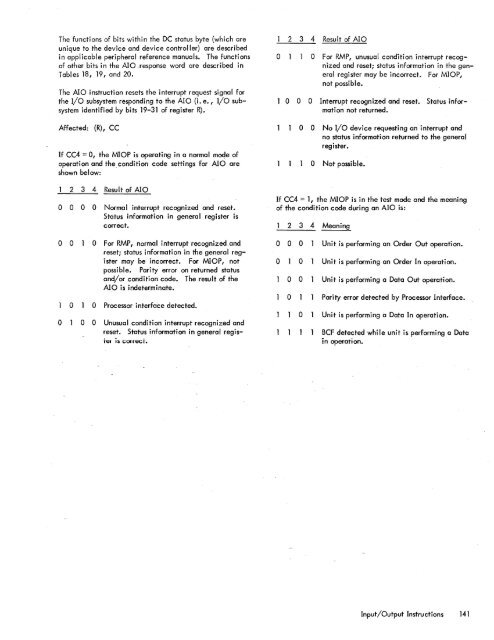
<strong>The</strong> functions of bits within the DC status byte (which areunique to the device and device controller) are describedin applicable peripheral reference manuals. <strong>The</strong> functionsof other bits in the Ala _response word are described inTables 18, 19, and 20.<strong>The</strong> Ala instruction resets the interrupt request signal forthe I/O sub<strong>system</strong> responding to the Ala (i.e., I/O sub<strong>system</strong>identified by bits 19-31 of register R).Affected: (R), CCIf CC4 = 0, the MIOP is operating in a normal mode ofoperation and thecondition code settings for Ala areshown below:2 3 4 Result of Alao 0 0 0 Normal interrupt recognized and reset.Status information in general register iscorrect.o 0 0 For RMP, normal interrupt recognized andreset; status information in the general registermay be incorrect. For MIOP, notpossible. Parity error on returned statusand/or condition code. <strong>The</strong> result of theAla is indeterminate.o 0 Processor interface detected.o 0 0 Unusual condition interrupt recognized andreset. Status information in general regisTel is (;orrecT.2 3 4 Result of Alao 0 For RMP, unusual condition interrupt recognizedand reset; status information in the generalregister may be incorrect. For MIOP,not possible.1 0 0 0 Interrupt recognized and reset. Status informationnot returned.o 0No I/O device requesting an interrupt andno status information returned to the generalregister.o Not possible.If CC4 = I, the MIOP is in the test mode and the meaningof the condition code during an Ala is:2 3 4 Meaning0 0 0 Unit is performing an Order Out operation.0 0 Unit is performing an Order In operation.0 0 Unit is performing a Data Out operation.0 Parity error detected by Processor Interface.0 Unit is performing a Data In operation.BCF detected while unit is performing a Datain operation.Input/Output Instructions 141
- Page 1 and 2:
Xerox 560 ComputerReference Manual9
- Page 5 and 6:
4. INPUT/OUTPUT OPERA TIO NS 142 AG
- Page 7 and 8:
1. XEROX 560 COMPUTER SYSTEMINTRODU
- Page 10 and 11:
Many operations are performed in fl
- Page 12 and 13:
Rapid Context Switching. When respo
- Page 14 and 15:
2. SYSTEM ORGANIZATIONThe elements
- Page 16:
FAST MEMORYARITHMETIC AND CONTROL U
- Page 19 and 20:
INFORMATION BOUNDARIESBasic process
- Page 21 and 22:
(Maximumof eight)Core Core Core Cor
- Page 23 and 24:
3. Diagnostic logic. Each memory dr
- Page 25 and 26:
eference address field of the instr
- Page 27 and 28:
Instruction in memory:Instruction i
- Page 29 and 30:
Real-extended addressing is specifi
- Page 31:
Table 1. Basic Processor Operating
- Page 35 and 36:
DesignationFunctionDesignationFunct
- Page 37 and 38:
InterruptStateDisarmedArmed[$Waitin
- Page 39 and 40:
AddressTable 2. Interrupt Locations
- Page 41 and 42:
is assumed to contain an XPSD or a
- Page 43 and 44:
Table 3. Summary of Trap LocationsL
- Page 45 and 46:
TRAP MASKSThe programmer may mask t
- Page 47 and 48:
PUSH-DOWN STACK LIMIT TRAPPush-down
- Page 49 and 50:
Instruction Name Mnemonic FaultDeci
- Page 51 and 52:
subroutine. However, with certain c
- Page 53 and 54:
3. INSTRUCTION REPERTOIREThis chapt
- Page 55 and 56:
CC1 is unchanged by the instruction
- Page 57 and 58:
Condition code settings:2 3 4 Resul
- Page 59 and 60:
Example 2, odd R field value:Before
- Page 61 and 62:
significance (FS), floating zero (F
- Page 63 and 64:
next sequential register after regi
- Page 65 and 66:
R 1 R2 R3 MeaningoThe effective vir
- Page 67 and 68:
Condition code settings:2 3 4 Resul
- Page 69 and 70:
MIMULTIPLY IMMEDIATE(Immediate oper
- Page 71 and 72:
original contents of register R, re
- Page 73 and 74:
Instruction NameCompare HalfwordMne
- Page 75 and 76:
Condition code settings:2 3 4 Resul
- Page 77 and 78:
2 3 4 Result of ShiftCircular Shift
- Page 79 and 80:
4. At the completion of the left sh
- Page 81 and 82:
Instruction NameFloating Subtract L
- Page 83 and 84:
The following table shows the possi
- Page 85 and 86:
Table 8.Condition Code Settings for
- Page 87 and 88:
PACKED DECIMAL NUMBERSAll decimal a
- Page 89 and 90:
DSTDECIMAL STORE(Byte index alignme
- Page 91 and 92:
If no indirect addressing or indexi
- Page 93 and 94:
Instruction NameMnemonicDesignation
- Page 95 and 96: Both byte strings are C bytes in le
- Page 97 and 98: of the destination byte that caused
- Page 99 and 100: again present, unti I a positive or
- Page 101 and 102: The new contents of register 7 are:
- Page 103 and 104: traps to location X'42 1 as a resul
- Page 105 and 106: If there is sufficient space in the
- Page 107 and 108: If CC1, or CC3, or both CC1 and CC3
- Page 109 and 110: appropriate memory stack locations
- Page 111 and 112: II, EI) are generated by II ORing"
- Page 113 and 114: In the real extended addressing mod
- Page 115 and 116: CAll INSTRUCTIONSEach ofthe four CA
- Page 117 and 118: The XPSD instruction' is used for t
- Page 119 and 120: If (I)1O = 0, trap or interrupt ins
- Page 121 and 122: For either memory map format and ei
- Page 123 and 124: initial value plus the initial valu
- Page 125 and 126: Table 9. Status Word 0Field Bits Co
- Page 127 and 128: READ INTERRUPT INHIBITSThe followin
- Page 129 and 130: Table 11.Read Direct Mode 9 Status
- Page 131 and 132: SET ALARM INDICATORThe following co
- Page 133 and 134: INPUT jOUTPUT INSTRUCTIONSThe I/o i
- Page 135 and 136: Table 13.Description of I/o Instruc
- Page 137 and 138: Table 15.Device Status Byte (Regist
- Page 139 and 140: Table 16. Operational Status Byte (
- Page 141 and 142: Table 19.Status Response Bits for A
- Page 143 and 144: If CC4 = 0, the MIOP is in a normal
- Page 145: 2 3 4 Meaningo 0 I/o address not re
- Page 149 and 150: 4. Each unit-record controller (int
- Page 151 and 152: Interrupt at Channel End (Bit Posit
- Page 153 and 154: Transfer in Channel. A control lOCO
- Page 155 and 156: Otherwise, the first word of the ne
- Page 157 and 158: Depending upon the characteristics
- Page 159 and 160: change the rate on the primary cons
- Page 161 and 162: Location(hex) (dec)20 3221 3322 342
- Page 163 and 164: Table 22.Diagnostic Control (P-Mode
- Page 165 and 166: at its normal rate (e. g., fixed du
- Page 167 and 168: SET LOW CLOCK MARGINSThis command c
- Page 169 and 170: BP STATUS AND NO.Th i s group of i
- Page 171 and 172: Input5MPri ntout5MFunctionStore X 1
- Page 173 and 174: 6. SYSTEM CONFIGURATION CONTROLPool
- Page 175 and 176: Table 25. Functions of Processor Cl
- Page 177: Table 26. Functions of Memory Unit
- Page 180 and 181: STANDARD 8-BIT COMPUTER CODES (EBCD
- Page 182 and 183: STANDARD SYMBOL-CODE CORRESPONDENCE
- Page 184 and 185: STANDARD SYMBOL-CODE CORRESPONDENCE
- Page 186 and 187: TABLE OF POWERS OF SIXTEEN II162564
- Page 188 and 189: HEXADECIMAL-DECIMAL INTEGER CONVERS
- Page 190 and 191: HEXADECIMAL-DECIMAL INTEGER CONVERS
- Page 192 and 193: HEXADECIMAL-DECIMAL INTEGER CONVERS
- Page 194 and 195: HEXADECIMAL-DECIMAL FRACTION CONVER
- Page 196 and 197:
HEXADECIMAL-DECIMAL FRACTION CONVER
- Page 198 and 199:
APPENDIX B.GLOSSARY OF SYMBOLIC TER
- Page 200 and 201:
TermMeaningTermMeaningWKxWrite key
- Page 202 and 203:
Table C-2. Memory Unit Status Regis
- Page 204 and 205:
Y OYf'lV r'f'lrnf'lrtil"\n'''' ....
- Page 206:
701 South Aviation BoulevardEI Segu