

1. xerox 560 computer system - The UK Mirror Service
1. xerox 560 computer system - The UK Mirror Service
1. xerox 560 computer system - The UK Mirror Service

You also want an ePaper? Increase the reach of your titles
YUMPU automatically turns print PDFs into web optimized ePapers that Google loves.
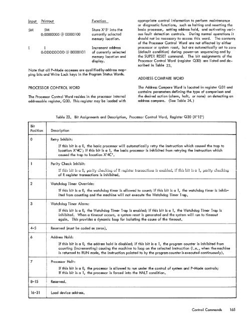
Input5MPri ntout5MFunctionStore X 1 5· into theappropriate control information to perform maintenanceor diagnostic functions, such as halting and resetting thebasic processor, setting address hold, and activating various0:00000005 @ 00000100 currently selectedfault detection controls. During normal operations itmemory location.should not be necessary to access this word. <strong>The</strong> contentsIIncrement addressof the Processor Control Word are not affected by eitherprocessor or <strong>system</strong> reset, but are automatically set to zeroO:DDDDDDDD @ 00000101 of currently selected (default condition) during power-on sequencing and bymemory I ocati on and the SUPER RESET command. <strong>The</strong> bit assignments of thedisplay.Processor Control Word (register Q30) are listed and describedin Table 23.Note that all P-Mode accesses are qualified by address mappingbits and Write Lock keys in the Program Status Words.ADDRESS COMPARE WORDPROCESSOR CONTROL WORD<strong>The</strong> Processor Control Word resides in the processor internaladdressable register, Q30. This register may be loaded with<strong>The</strong> Address Compare Word is located in register Q31 andcontains parameters defining the type of comparison andthe desired action (alarm, halt, or none) on detecting anaddress compare. (See Table 24.)Table 23. Bit Assignments and Description, Processor Control Word, Register Q30 (XI lEI}BitPositionDescription0 Retry Inhibit:If this hit is a 0, the basic processor will automatically retry the instruction which caused the trap tolocation X'4C '; if this bit is a 1, the basic processor is inhibited from retrying the instruction whichcaused the trap to location X'4C ' •1 Parity Check Inhibit:11" .... L!_ L!.J.. ! ___ f\ _____ !.L ___ L __ L! ____ £ n ____ !_L __ L _______ L! ____ ! ____ LI_-<strong>1.</strong> !£ LL!_ L!.L ! __ 1___ !L ___ L __ I_! __11 1111;) Uti I;) U v, fJUIIIY '-'11~'-'''''III~ VI 1'<strong>1.</strong> I~~';)I~I IIUIIO>U'-'"VII;) I;) ~IIU"""~"" .. 1111;) ...... I;) Uof R register transactions is inhibited.2 Watchdog Timer Override:"PUI,'Y '-'""~'-'''''."'~If this bit is a 0, the watchdog timer is allowed to count; if this bit is a 1, the watchdog timer is inhibitedfrom counting and the machine will not execute the Watchdog Timer Trap.3 Watchdog Timer Alarm:If this bit is a 0, the Watchdog Timer Trap is enabled; if this bit is a 1, the Watchdog Timer Trap isinhibited. When a timeout occurs, a <strong>system</strong> reset is generated and the <strong>system</strong> will run to timeoutagain. This provides a dynamic loop for isolating the cause of the timeout.4-5 Reserved {must be coded as zeros}.6 Address Hold:7 Processor Ha It:8-15 Reserved.If this bit is a 0, the address hold is disabled; if this bit is a 1, the program counter is inhibited fromcounting {incrementing} causing the machine to loop on the selected instruction (i. e., when the machineis returned to RUN mode, the instruction pointed to by the program counter is executed continuously).If this bit is a 0, the processor is allowed to run under the control of <strong>system</strong> and P-Mode controls;If this bit is a 1, the processor is forced into the HALT condition.16-31 Load device address.Control Commands 165


