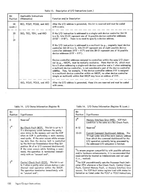
Table 13. Description of I/O Instructions (cont.)Bit Applicable InstructionsPosition (Mnemonics) Function and/or Description24 RIO, POlP, POlR, and AlO After the I/O address is generated, this bit is reserved and must be coded(cont.)with a zero.'"--- ~---- - ---------------------2531510, TIO, TDV, and HIO If the I/o instruction is addressed to a single-unit device controller (bit 24is a D), bits 25-31 represent one of 16 possible device controller addresses(X'OO' - X'OF'). <strong>The</strong>re is no need to specify a device address.If the I/o instruction is addressed to a multiunit (e. g., magnetic tape) devicecontroller (bit 24 is a 1), bits 25-27 represent one of eight possible devicecontroller addresses (X'D' - X'7') and bits 28-31 represent one of 16 possibledevice addresses (X'D' - X'FI).Device controller addresses assigned to controllers within the same I/O channel(e. g., MIOP), must be mutually exclusive. Note that bit 24, which mustbe a 0 when addressing a single-unit device controller and a 1 when addressinga multiunit device controller, is not considered a part of the decive controlleraddr~ss. Thus, for example, if the device controller address X'D' is assignedto a multiunit device controller within an MIOP, no other device controller(single or multiunit) within that MIOP may have an address of XIOI.-- - - - -- - - - - - - - - - - - - - - - ---RIO, POlP, POlR, and AIOAfter the I/o address is generated, these bits are reserved and must be codedwith zeros.Table 14. I/o Status Information (Register R)Table 14. I/o Status Information (Register R) (cont.)BitBitPosition Significance Position SignificanceoReserved tBus Check Fault (BCF). This bit is set to 1if a discrepancy exists between the parityerror status in the memory unit and the lOPwhen an lOP is performing a main memoryread cycle. If the error occurs whi Ie accessingdata then the devi ce halt is controlledby the Halt-on-Transmission-Error flag (bitposition 36 of an I/O command doubleword).If the error occurs whi Ie fetching a command,the operation is terminated immediatelywith an "unusual end ll •Control Check Fault (CCF). This bit is setto 1 when a parity error occurs during a subchannelread operation within the MIOP.<strong>The</strong> operation terminates immediately withan "unusual end".3 tt Memory Interface Error (MIE). lOP Haltcondition is the same as a Bus Check Fault.4-1213-31Reserved tCurrent Command Doubl eword Address. <strong>The</strong>19 high-order bits of the main memory addressfrom which the command doubleword for theI/o operation currently being processed bythe addressed I/O sub<strong>system</strong> is fetched.tTo ensure program compatibility with possible softwareand/or hardware enhancements, it is recommended thatreserved bits be treated as indeterminate and not used(L e, i masked),tt<strong>The</strong> lOP unconditionally sets the Processor Fault Indicator(PFI) whenever a Bus Check Fault, Control CheckFault, Control Memory Fault, or Memory Interface Erroroccurs. <strong>The</strong> lOP fault status registerisset with status informationas listed under the POlP or POlR instructions.130 Tnput/Output Instruction
Table 15.Device Status Byte (Register R or Rul)(510, no, and HIO only)Table 15. Device Status Byte (Register R or Ru1)(510, no, and HIO only) (cont.)BitPositionSignificanceBitPositionSignificancea1,2Interrupt Pending. This bit is set to a 1 ifthe addressed device has requested an interruptthat has not been acknowl edged by theBP with an AIO instruction. If this bit isa 1, the current 510 instruction is not accepted.Condition code bits are set to reflectthis action and any requested statusinformation is loaded into the designatedgeneral register(s). 510 instructions wi II notbe accepted unti I the interrupt pendi ng conditionis cleared.Normally, before a device can request aninterrupt, the following conditions mustprevail:<strong>1.</strong> Appropriate flag(s) (IZC, ICE, and/orIUEi bit positions 33, 35, and 37, respectively)within the I/o commanddoubleword must be set to <strong>1.</strong>2. <strong>The</strong> flagged event (byte count reducedto zero for the IZC flag, "channel end"condition for the ICE flag, or "unusualend" condition for the IUE flag) mustoccur.3. lOP may signal device controller to__ ~ __ !_"" ___.._" ... :""L_.. .a.IUI~v_,,_ .......:_:__ :_""_ ... _IIIICI'VtJl YYIIIIVVI "''''...... III1II<strong>1.</strong>I~ 1'11,,-,"1rupt flags, if:a. A connection address error isdetected.b. Any error is detected when lOP isaccessing an IOCD.For case a, no interrupt status wi II beset in response to an AIO.For case b, an IUE signal is sent backin response to an AIO.An I/O interrupt may also be requested bycertain devices via M modifier bits withinthe basic order for that device (see OperationalCommand Doublewords).A BP wi II respond to an interrupt requestfrom a particular I/O sub<strong>system</strong> if (1) theI/O interrupt level (X I 5C') is armed, enabled,and not inhibited; and (2) that thereis no higher priority interrupt level in theactive or waiting state.Device Condition. If bits 1 and 2 are 00 (device"ready"), all device conditions required1,2(cont. )3for proper operation are satisfied. If bits 1and 2 are 01 (device "not operational"), theaddressed device has developed some conditionthat wi II not allow it to proceed; ineither case, operator intervention is usuallyrequired. If bits 1 and 2 are 10 (device "unavailable"), the device has more than onechannel of communication available and it isengaged in an operation controlled by a controllerother than the one specified by theI/O address. If bits 1 and 2 are 11 (device"busy "), the device has accepted a previous510 instruction and is already engaged in anI/O operation.Device Mode. If this bit is 1, the device isin the "automatic" mode; if this bit is a, thedevice is in the "manual" mode and requiresoperator intervention. This bit can be usedin conjunction with bits 1 and 2 to determinethe type of action required. For example,assume that a card reader is able to operate,but no cards are in the hopper. <strong>The</strong> cardreader would be in state 000 (device "ready",but manual intervention required), wherethe state is indicated by bits 1, 2, and 3 ofthe I/O status response. If the operator subsequentlyloads the card hopper and pressesthe card reader START switch, the readerwould advance to state 001 (device "ready"and in automatic operation). If the cardreader is in state 000 when an 510 instructionis executed, the 510 would be acceptedby the reader and the reader would advanceto state 110 (device "busy", but operator interventionrequired). Should the operatorthen place cards in the hopper and press theSTART switch, the card reader state wouldadvance to 111 (device II busy II and in "automatic"mode), and the input operation wouldproceed. Should the card reader subsequentlybecome empty (or the operator press theSTOP switch) and command chaining is beingused to read a number of cards, the cardreader would return to state 110. If the cardreader is in state 001 when an 510 instructionis executed, the reader advances tostate 111, and the input operation continuesas normal. Should the hopper subsequentlybecome empty (or should the operator pressthe card reader STOP switch) and commandchaining is being used to read a number ofcards, the reader would go to state 110 unti Ithe operator corrected the situation.For RMP, this bit is always set to one.Input/Output Instructions 131
- Page 1 and 2:
Xerox 560 ComputerReference Manual9
- Page 5 and 6:
4. INPUT/OUTPUT OPERA TIO NS 142 AG
- Page 7 and 8:
1. XEROX 560 COMPUTER SYSTEMINTRODU
- Page 10 and 11:
Many operations are performed in fl
- Page 12 and 13:
Rapid Context Switching. When respo
- Page 14 and 15:
2. SYSTEM ORGANIZATIONThe elements
- Page 16:
FAST MEMORYARITHMETIC AND CONTROL U
- Page 19 and 20:
INFORMATION BOUNDARIESBasic process
- Page 21 and 22:
(Maximumof eight)Core Core Core Cor
- Page 23 and 24:
3. Diagnostic logic. Each memory dr
- Page 25 and 26:
eference address field of the instr
- Page 27 and 28:
Instruction in memory:Instruction i
- Page 29 and 30:
Real-extended addressing is specifi
- Page 31:
Table 1. Basic Processor Operating
- Page 35 and 36:
DesignationFunctionDesignationFunct
- Page 37 and 38:
InterruptStateDisarmedArmed[$Waitin
- Page 39 and 40:
AddressTable 2. Interrupt Locations
- Page 41 and 42:
is assumed to contain an XPSD or a
- Page 43 and 44:
Table 3. Summary of Trap LocationsL
- Page 45 and 46:
TRAP MASKSThe programmer may mask t
- Page 47 and 48:
PUSH-DOWN STACK LIMIT TRAPPush-down
- Page 49 and 50:
Instruction Name Mnemonic FaultDeci
- Page 51 and 52:
subroutine. However, with certain c
- Page 53 and 54:
3. INSTRUCTION REPERTOIREThis chapt
- Page 55 and 56:
CC1 is unchanged by the instruction
- Page 57 and 58:
Condition code settings:2 3 4 Resul
- Page 59 and 60:
Example 2, odd R field value:Before
- Page 61 and 62:
significance (FS), floating zero (F
- Page 63 and 64:
next sequential register after regi
- Page 65 and 66:
R 1 R2 R3 MeaningoThe effective vir
- Page 67 and 68:
Condition code settings:2 3 4 Resul
- Page 69 and 70:
MIMULTIPLY IMMEDIATE(Immediate oper
- Page 71 and 72:
original contents of register R, re
- Page 73 and 74:
Instruction NameCompare HalfwordMne
- Page 75 and 76:
Condition code settings:2 3 4 Resul
- Page 77 and 78:
2 3 4 Result of ShiftCircular Shift
- Page 79 and 80:
4. At the completion of the left sh
- Page 81 and 82:
Instruction NameFloating Subtract L
- Page 83 and 84:
The following table shows the possi
- Page 85 and 86: Table 8.Condition Code Settings for
- Page 87 and 88: PACKED DECIMAL NUMBERSAll decimal a
- Page 89 and 90: DSTDECIMAL STORE(Byte index alignme
- Page 91 and 92: If no indirect addressing or indexi
- Page 93 and 94: Instruction NameMnemonicDesignation
- Page 95 and 96: Both byte strings are C bytes in le
- Page 97 and 98: of the destination byte that caused
- Page 99 and 100: again present, unti I a positive or
- Page 101 and 102: The new contents of register 7 are:
- Page 103 and 104: traps to location X'42 1 as a resul
- Page 105 and 106: If there is sufficient space in the
- Page 107 and 108: If CC1, or CC3, or both CC1 and CC3
- Page 109 and 110: appropriate memory stack locations
- Page 111 and 112: II, EI) are generated by II ORing"
- Page 113 and 114: In the real extended addressing mod
- Page 115 and 116: CAll INSTRUCTIONSEach ofthe four CA
- Page 117 and 118: The XPSD instruction' is used for t
- Page 119 and 120: If (I)1O = 0, trap or interrupt ins
- Page 121 and 122: For either memory map format and ei
- Page 123 and 124: initial value plus the initial valu
- Page 125 and 126: Table 9. Status Word 0Field Bits Co
- Page 127 and 128: READ INTERRUPT INHIBITSThe followin
- Page 129 and 130: Table 11.Read Direct Mode 9 Status
- Page 131 and 132: SET ALARM INDICATORThe following co
- Page 133 and 134: INPUT jOUTPUT INSTRUCTIONSThe I/o i
- Page 135: Table 13.Description of I/o Instruc
- Page 139 and 140: Table 16. Operational Status Byte (
- Page 141 and 142: Table 19.Status Response Bits for A
- Page 143 and 144: If CC4 = 0, the MIOP is in a normal
- Page 145 and 146: 2 3 4 Meaningo 0 I/o address not re
- Page 147 and 148: The functions of bits within the DC
- Page 149 and 150: 4. Each unit-record controller (int
- Page 151 and 152: Interrupt at Channel End (Bit Posit
- Page 153 and 154: Transfer in Channel. A control lOCO
- Page 155 and 156: Otherwise, the first word of the ne
- Page 157 and 158: Depending upon the characteristics
- Page 159 and 160: change the rate on the primary cons
- Page 161 and 162: Location(hex) (dec)20 3221 3322 342
- Page 163 and 164: Table 22.Diagnostic Control (P-Mode
- Page 165 and 166: at its normal rate (e. g., fixed du
- Page 167 and 168: SET LOW CLOCK MARGINSThis command c
- Page 169 and 170: BP STATUS AND NO.Th i s group of i
- Page 171 and 172: Input5MPri ntout5MFunctionStore X 1
- Page 173 and 174: 6. SYSTEM CONFIGURATION CONTROLPool
- Page 175 and 176: Table 25. Functions of Processor Cl
- Page 177: Table 26. Functions of Memory Unit
- Page 180 and 181: STANDARD 8-BIT COMPUTER CODES (EBCD
- Page 182 and 183: STANDARD SYMBOL-CODE CORRESPONDENCE
- Page 184 and 185: STANDARD SYMBOL-CODE CORRESPONDENCE
- Page 186 and 187:
TABLE OF POWERS OF SIXTEEN II162564
- Page 188 and 189:
HEXADECIMAL-DECIMAL INTEGER CONVERS
- Page 190 and 191:
HEXADECIMAL-DECIMAL INTEGER CONVERS
- Page 192 and 193:
HEXADECIMAL-DECIMAL INTEGER CONVERS
- Page 194 and 195:
HEXADECIMAL-DECIMAL FRACTION CONVER
- Page 196 and 197:
HEXADECIMAL-DECIMAL FRACTION CONVER
- Page 198 and 199:
APPENDIX B.GLOSSARY OF SYMBOLIC TER
- Page 200 and 201:
TermMeaningTermMeaningWKxWrite key
- Page 202 and 203:
Table C-2. Memory Unit Status Regis
- Page 204 and 205:
Y OYf'lV r'f'lrnf'lrtil"\n'''' ....
- Page 206:
701 South Aviation BoulevardEI Segu